Viewer
The viewer is a library, not an app: design code builds a Scene (parts grouped
into tabs) and hands it over. EngrCad.Show(scene) opens the interactive window;
EngrCad.ShowLive(factory) adds the hot-reload loop; EngrCad.RenderToImage renders
headless PNGs — which is how every screenshot in these docs is made.
var scene = new Scene(new MeshQuality { SegmentsPerCircle = 48 });
var housing = scene.AddTab("housing");housing.Add(new Part("body",    Shape.Extrude(Sketch.RoundedRectangle(60, 40, 8), 20)        .Fillet(3, s => s.PlanarFacesWithNormal(Vector3d.UnitZ)),    Palette.Steel));housing.Add(new Part("boss", Shape.Cylinder(9, 12), Palette.Brass,    Matrix4d.CreateTranslation((0, 0, 24))));housing.Add(new Part("pins", Shape.Cylinder(2.5, 10).Translate(22, 12, 22)    .PatternLinear(2, (0, -24, 0)), Palette.Coral));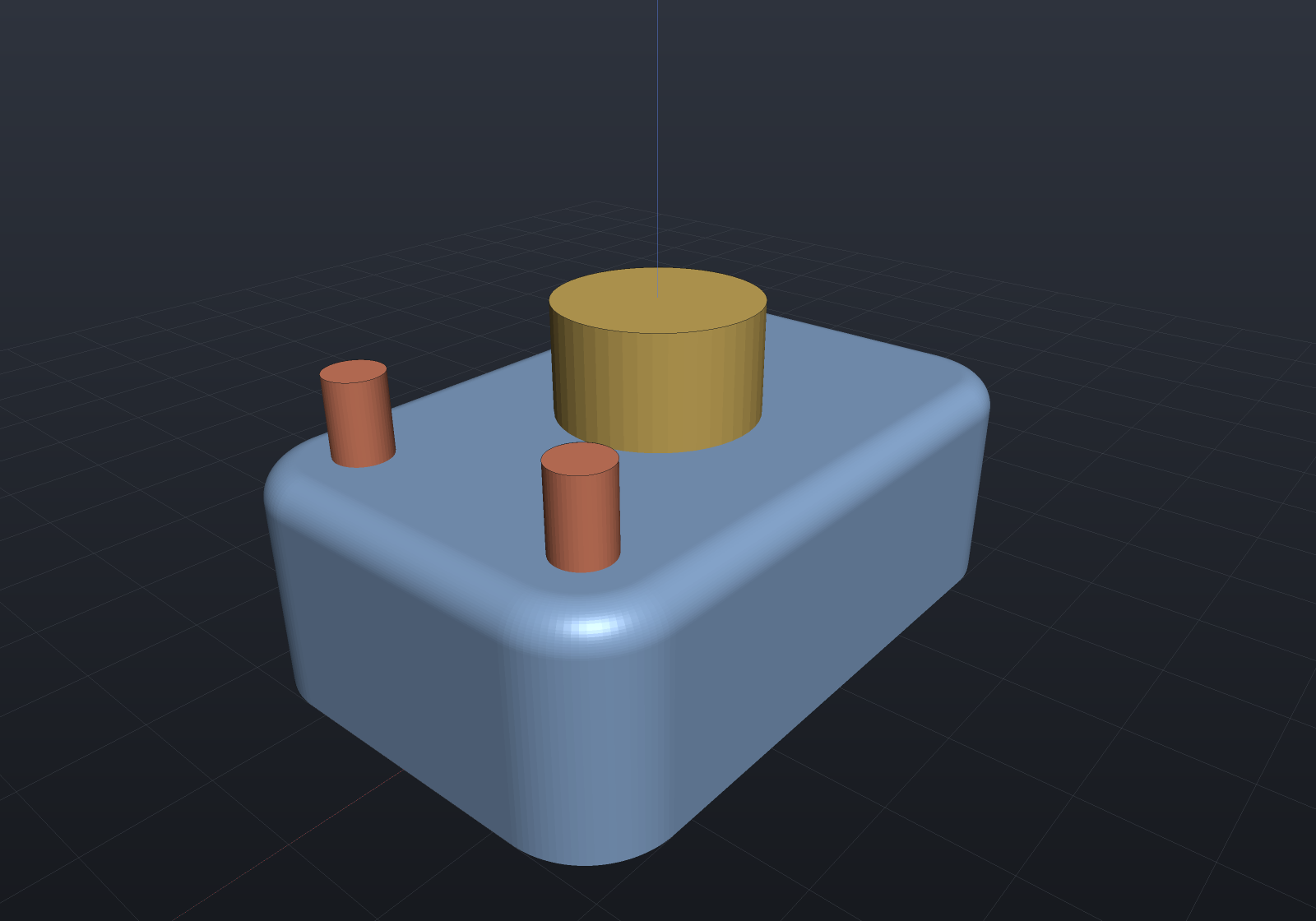
The interactive window adds the CAD chrome around this same rendering: toolbar (Fit, Front/Top/Right/Iso views, perspective/orthographic toggle), model tree with visibility checkboxes and two-way selection sync, properties panel (volume, area, face count), click-picking by part name, adaptive ground grid with RGB axes, and a feature-edge overlay — the classic shaded-with-edges CAD look.
EngrCad.Show(scene, "housing"); // blocking; one call per processreturn EngrCad.Run(args, BuildScene, "housing"); // live loop + --view/--export/--renderPer-part display modes
Part.DisplayMode selects Shaded (lit fill + feature edges), Wireframe
(every mesh edge as a line, no fill), or Translucent (alpha-blended fill with
opaque silhouette edges — see through a housing to its contents). Each model-tree row
has a shade/wire/glass cycler, and design code can set it directly:
housing.Add(new Part("cover", coverShape, Palette.Sky) { DisplayMode = DisplayMode.Translucent });Display modes are honored by both render paths — the interactive viewport and the
offscreen renderer these docs use draw with the same shaders and mode-precedence
rule, alongside a global view style (ViewportControl.ViewStyle, or
--render-style points|wireframe|shaded|shaded-edges for headless renders): parts
left at the default follow the global style, explicitly non-default parts keep
their own mode.
Matcap shading
The Shading dropdown (or EngrCad.Configure().WithShading(...), or the
shading: parameter on headless renders and the MCP screenshot tool) swaps the
standard directional light for an analytic matcap — a studio lit-sphere look
evaluated procedurally in the shared mesh shader, so no texture ever has to reach
the window, the offscreen renderer or the browser client. ShadingStyle.Clay is
the matte studio sphere; ShadingStyle.Metal the polished-metal one. Shading is
deliberately separate from the view style: the style says what is drawn (points,
lines, fills), shading says how a fill is lit, and the two compose. It is global
per pass — there is no per-part override, because a scene lit two ways reads as a
rendering bug.
// A render: snippet declares `shading` the way it declares `camera` or `explode`.var shading = ShadingStyle.Metal;
var scene = new Scene(new MeshQuality { SegmentsPerCircle = 64 });scene.Add(new Part("plate", Shape.Box(60, 40, 10) - Shape.Cylinder(6, 30), Palette.Steel));scene.Add(new Part("dome", Shape.Sphere(12), Palette.Brass,    Matrix4d.CreateTranslation((18, 0, 14))));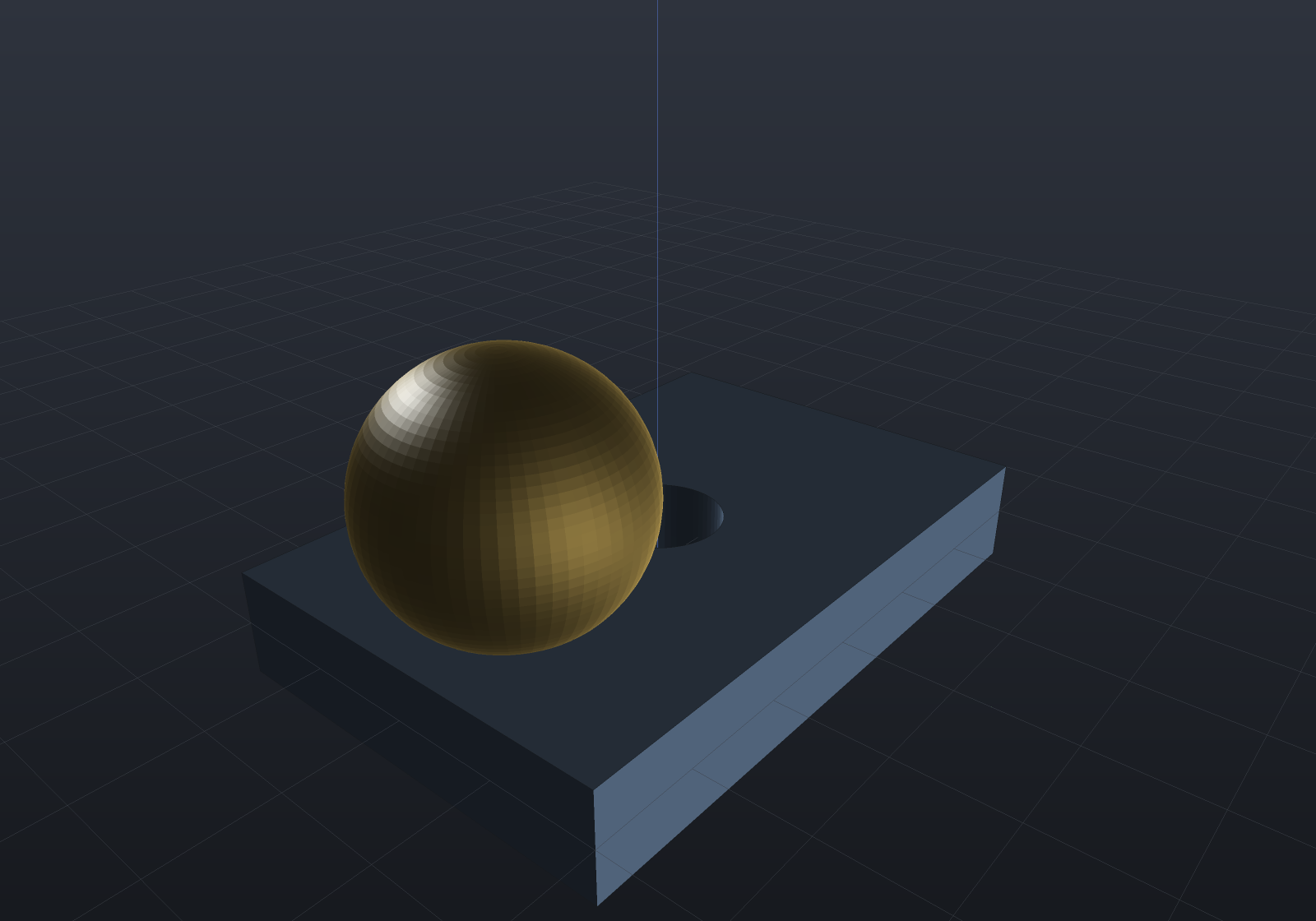
Ambient occlusion multiplies the matcap sample exactly as it multiplies the
standard ambient+diffuse product, section cut faces keep their flat cut material,
and selection gold blends the same way — a matcap changes how a fill is lit and
nothing else. The default (ShadingStyle.Lit) is pixel-identical to the viewer
before the feature existed.
Debug modifiers (ghost, hide, isolate)
Three part-level flags — the OpenSCAD %/*/! analog — mark parts while you
debug a model, honored by the window, headless renders and every exporter through
one shared rule set (DebugFilter):
part.Ghost = true(%background) — rendered translucent for reference, excluded from geometry exports: jigs, envelopes, reference bodies you want to see but never print.part.Hidden = true(*disable) — not rendered, not exported, but still in the model tree.part.Isolated = true(!root) — when any part is isolated, only isolated parts show and export.
// The envelope is a ghost: visible as translucent context, absent from any// --export file. The bracket is the real part.var scene = new Scene();scene.Add(new Part("bracket", Shape.Box(40, 24, 8) - Shape.Cylinder(6, 20), Palette.Steel));var envelope = scene.Add(new Part("clearance envelope", Shape.Box(56, 40, 24), Palette.Sky));envelope.Ghost = true;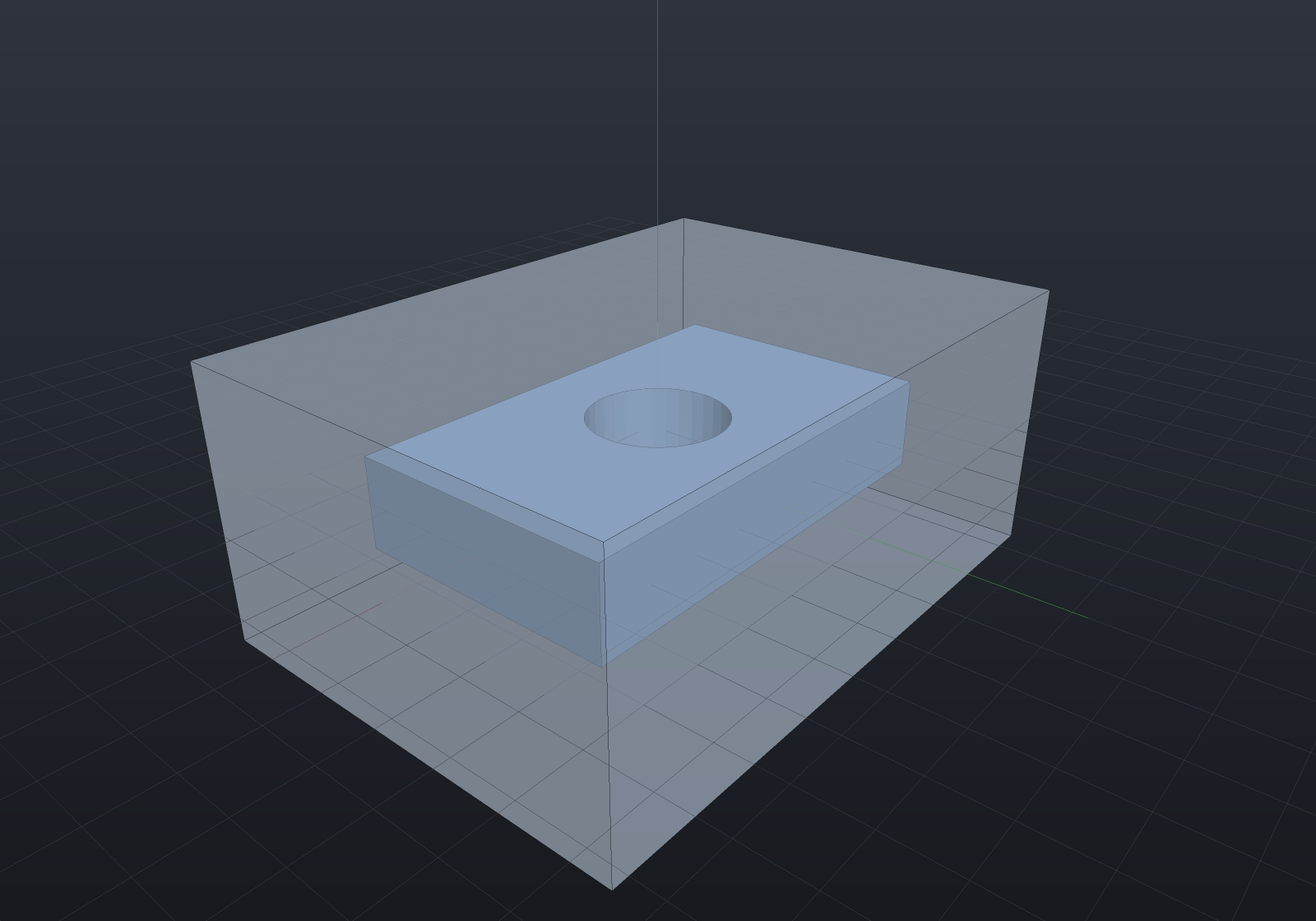
The validation report (Check)
The toolbar’s Check button — or SceneReport.Create(scene) in code, the
assert/echo analog — reports every part’s kind, face count, watertightness,
volume, surface area and size, with notes naming anything suspicious: an open mesh
(with its boundary-loop count), a part that failed to mesh (the exception becomes a
named note, not a crash), a non-positive volume, active debug modifiers. Scripts
assert on it:
var scene = new Scene();scene.Add(new Part("plate", Shape.Box(60, 40, 8) - Shape.Cylinder(5, 20)));scene.Add(new Part("boss", Shape.Cylinder(8, 14)));
var report = SceneReport.Create(scene);Console.WriteLine(report.ToText());if (!report.AllClean) throw new Exception("expected a clean model");if (report.Parts.Any(p => !p.Closed)) throw new Exception("everything should be watertight");
Section planes
The toolbar’s Section toggle clips everything beyond an axis-aligned plane —
X, Y, or Z (a toolbar cycler picks the axis, [ / ] keys nudge the offset) —
exposing interiors with a flat darker “cut material” on the revealed surfaces: the
standard way to inspect bores, cavities, and fillets in cross-section. Custom hosts
drive it via ViewportControl.SectionEnabled / SectionAxis / SectionOffset.
The render below uses the real section plane (the geometry is untouched — the
clipping happens in the shader), exactly what --section z 6 produces headlessly:
var block = Shape.Box(40, 40, 24)    .SmoothUnion(Shape.Sphere(10).Translate(0, 0, 14), 5)    - Shape.Cylinder(6, 60)                       // vertical bore    - Shape.Cylinder(5, 60).RotateX(Math.PI / 2); // horizontal bore
var scene = new Scene(new MeshQuality { SdfResolution = 140 });scene.Add(new Part("block", block, Palette.Steel,    Matrix4d.CreateTranslation((0, 0, 12))));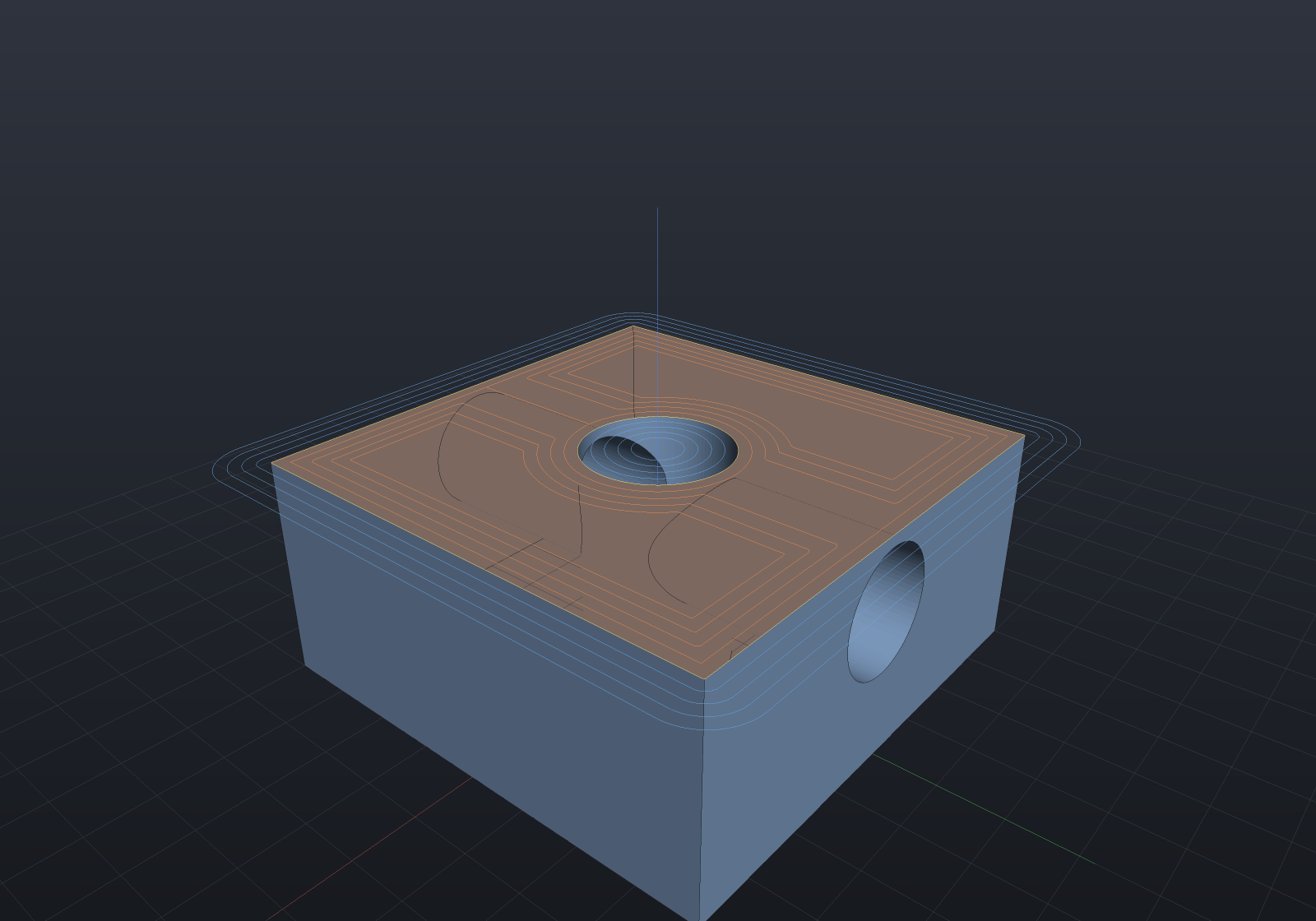
Several planes, and oblique ones
Up to four section planes combine at once. SectionCombine.Intersection (the
default) clips only where every plane excludes, which gives the classic quarter
cut from two perpendicular planes and an octant from three; Union clips where
any does. With a single plane the two rules coincide.
Planes need not be axis-aligned — SectionPlane.Through(point, normal) takes any
normal, and SectionPlane.On(frame) any Frame3d. Fence options only spell
axis-aligned cuts, so a snippet declares the list itself:
var housing = Shape.Box(44, 44, 30)    - Shape.Cylinder(13, 40)                                  // main bore    - Shape.Cylinder(5, 60).RotateY(Math.PI / 2);             // cross bore
var scene = new Scene();scene.Add(new Part("housing", housing, Palette.Steel));
// Quarter cut, rotated 30 degrees about Z: two perpendicular oblique planes.double a = Math.PI / 6;var sectionPlanes = new[]{    SectionPlane.Through((0, 0, 0), (Math.Cos(a), Math.Sin(a), 0)),    SectionPlane.Through((0, 0, 0), (-Math.Sin(a), Math.Cos(a), 0)),};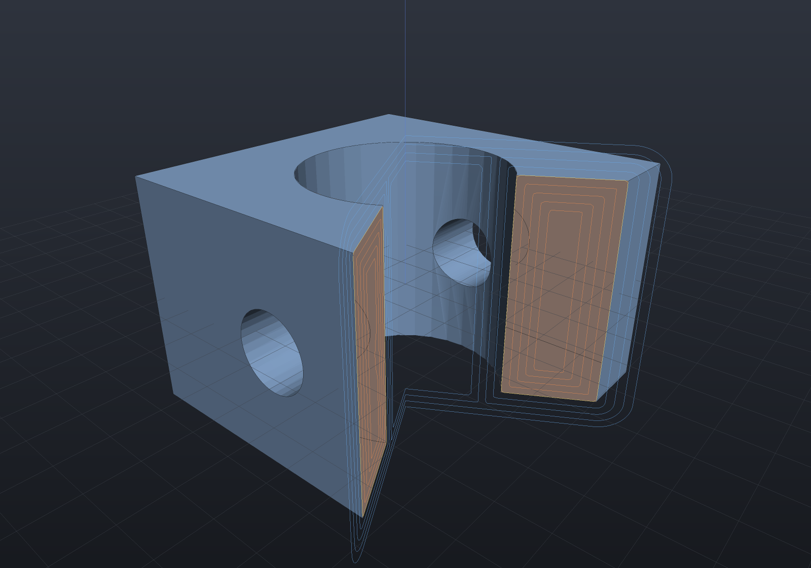
A render: snippet may declare sectionPlanes (any IEnumerable<SectionPlane>),
sectionCombine, and camera alongside its scene — the same convention scene
already uses. They win over the fence’s section: option, which stays the short
spelling for the common axis-aligned case.
Hardware is drawn unsectioned
Part.ClippedBySection = false renders and picks a part whole inside a cutaway.
That is not a rendering trick but a drafting rule: bolts, screws, nuts, keys, pins and
other solid fasteners are drawn unsectioned, because cutting a solid fastener
lengthwise shows nothing and only clutters the section. HardwareComponent.ToPart()
sets it for you, so a sectioned assembly shows its housing cut open with the fasteners
standing whole in their (sectioned) holes:
var top = SketchPlane.At((0, 0, 6), Vector3d.UnitX, Vector3d.UnitY);
var build = new ComponentAssembly("plate", Shape.Box(70, 40, 12), Palette.Sage);build.Place(StandardComponents.CapScrew(5, 16), [new(-22, 0), new(22, 0)], top);
var scene = new Scene();scene.AddTab("cut").Add(build.ToAssembly("bracket"));
var sectionPlanes = new[] { SectionPlane.On(SectionAxis.Y, 0) };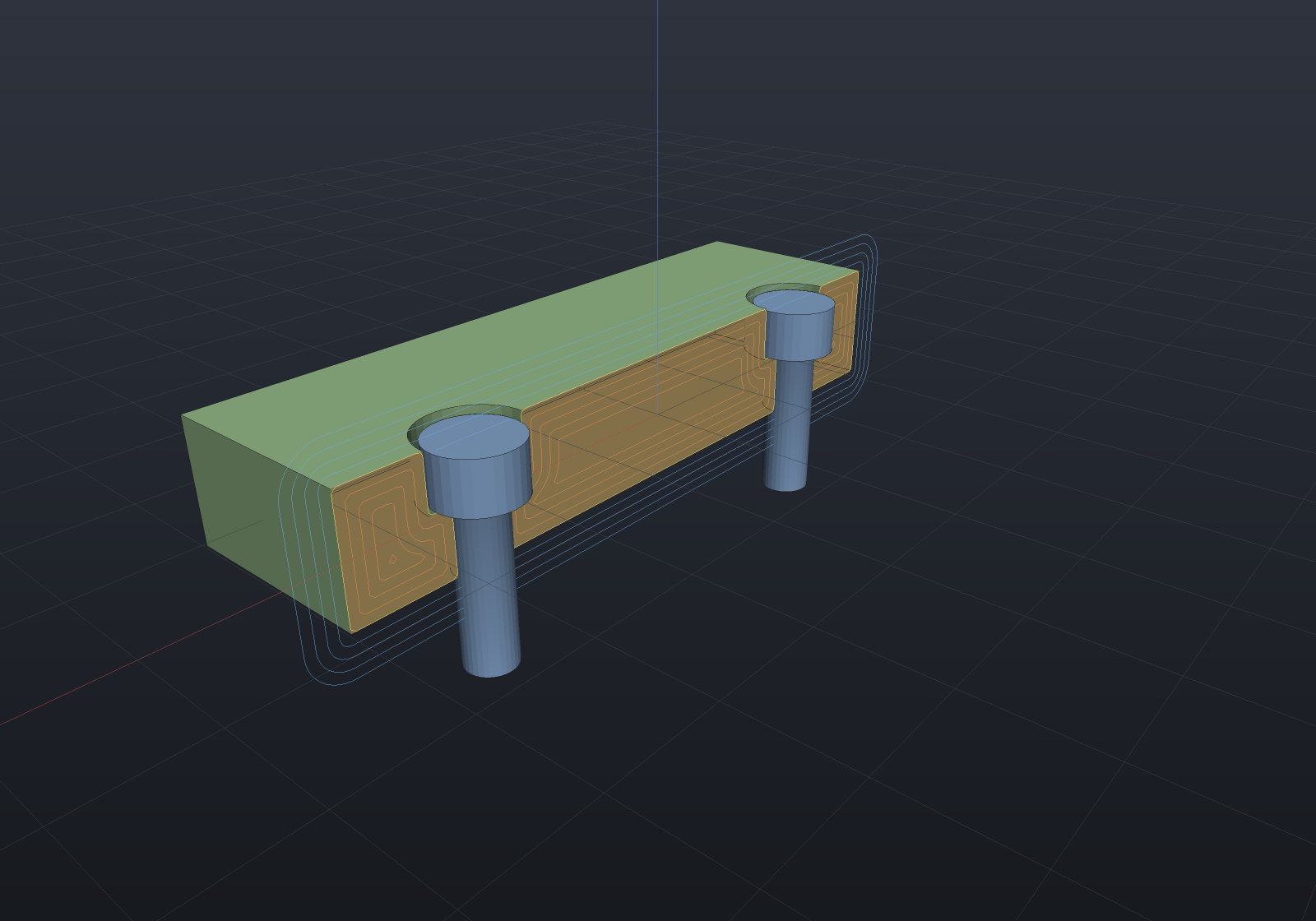
SDF isolines on the cut
Parts whose geometry is an Sdf — or a Shape with an implicit lowering, which is
most of them — automatically get iso-distance contours overlaid on the section
plane: the gold contour is the exact d = 0 surface cross-section, cool rings march
outward at +k·spacing, warm rings inward at −k·spacing. Wall thickness is readable
at a glance, and smooth blends and offsets show their actual field, which makes the
overlay a debugging tool as much as a display nicety:
var body = Shape.Cylinder(16, 26)    .SmoothUnion(Shape.Sphere(13).Translate(0, 0, 28), 9)   // blend-heavy top    - Shape.Cylinder(8, 90);                                // through-bore
var scene = new Scene(new MeshQuality { SdfResolution = 200 });scene.Add(new Part("blend", body, Palette.Steel));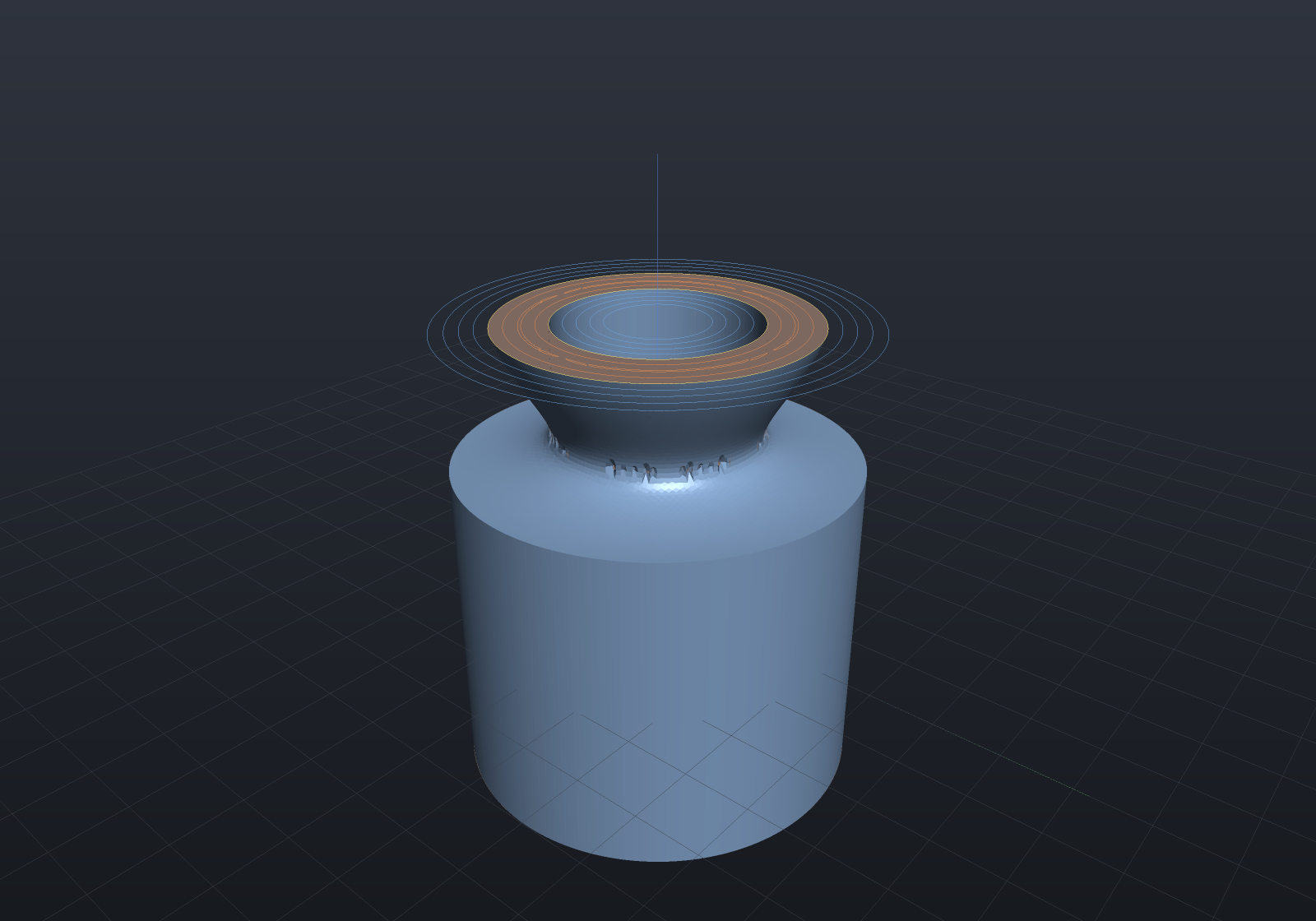
Construction previews
Every Shape part expands in the model tree into how it was built — the
operation graph as nested rows (a FeatureHistory part shows its feature list).
Clicking a row previews that step in the viewport: the model as of that step, a
rollback view, drawn as construction-cyan edges over the finished part.
Headless renders can draw the same overlay. A render: snippet (or any
EngrCad.RenderToImage caller) declares a preview — the part plus the
construction-tree row to show, addressed by its stable positional path:
// A boss on a plate, then a bore through both.var body = (Shape.Box(60, 40, 10) | Shape.Cylinder(12, 14).Translate(0, 0, 8))    - Shape.Cylinder(6, 60);
var part = new Part("bracket", body, Palette.Steel);var scene = new Scene();scene.Add(part);
// Row "0" is the union — the body BEFORE the bore. Previewing it overlays that// step's feature edges on the finished part: the rollback view, in a still image.var preview = new ConstructionPreviewRequest(part, part.ConstructionTree()!.Find("0")!);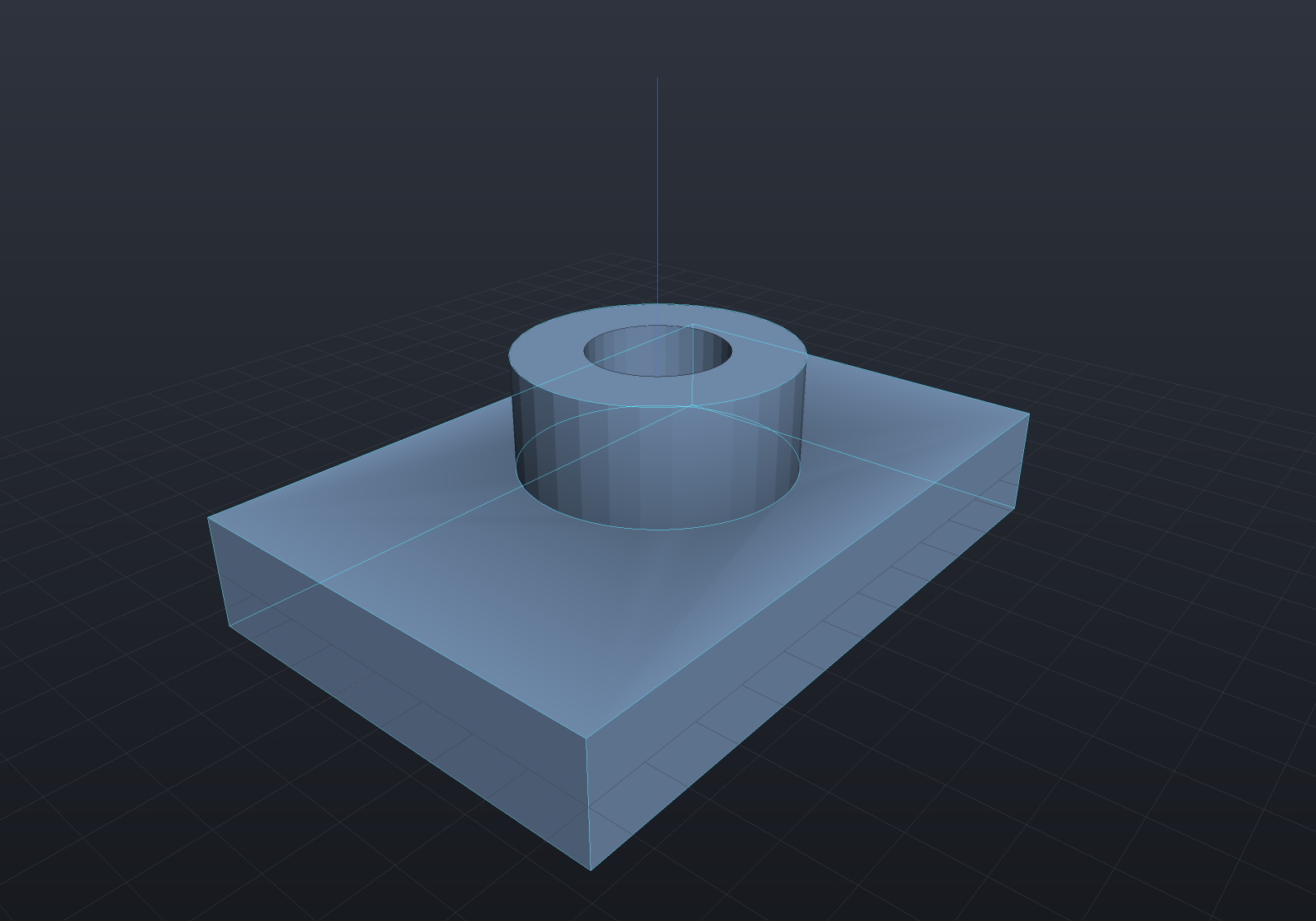
The overlay draws through the same PreviewLayer the window uses (always on top,
never section-clipped), so the two paths cannot drift; a row that cannot be lowered
fails the render rather than silently omitting the overlay. In the window, the
tree rows of a feature-history part additionally carry a suppress toggle, a rollback
marker, and editable [Param] fields in the properties panel — see the
parametric features page.
Undo and redo
Both model edits the window offers — the per-row suppress toggle and the properties
panel’s [Param] fields — go through the document edit vocabulary described on the
documents page, so the toolbar’s Undo / Redo buttons (and
Ctrl+Z / Ctrl+Y, or
Ctrl+Shift+Z) take them back. The buttons name the step
they would undo in their tooltip.
A parameter that breaks the rebuild is refused rather than left applied: the value goes back, the model rebuilds, the status bar says why, and nothing lands on the undo stack. The rollback marker is deliberately outside the stack — it carries its own per-part suppression bookkeeping — and stays a direct edit.
The shortcut handler bubbles and does not claim already-handled events, unlike the viewport’s pointer handlers. A focused text field has its own undo; taking Ctrl+Z away from it while you were typing a value would be worse than missing the shortcut.
Headless rendering
EngrCad.RenderToImage(scene, path, width, height, camera?, style?, sectionAxis?, sectionOffset?) renders with no window and no Avalonia lifetime — an offscreen EGL
pbuffer over the ANGLE runtime, with a software (WARP) fallback for CI. Check
EngrCad.CanRenderToImage to skip gracefully on machines with no GL at all. This is
the self-verification loop: tests and agents render a scene and inspect pixels
instead of screenshotting a window. Headless renders match the window — display
modes, view styles, section planes, and the SDF isolines above all render
identically (only interactive selection highlights are absent).
if (EngrCad.CanRenderToImage) EngrCad.RenderToImage(scene, "out.png", width: 1280, height: 800, sectionAxis: SectionAxis.Z, sectionOffset: 6); // optional real section planeThe interactive window’s Capture toolbar button (or
ViewportControl.SaveScreenshot) saves the current framebuffer the same way. That
call is fire-and-forget — the capture happens in the next render pass, so the path
it names is a promise. A caller that intends to read the file back wants
ViewportControl.CaptureScreenshotAsync(path?), whose Task<string> completes once
the PNG has been written; it is what the MCP viewer_screenshot bridge tool waits on
before returning the image.