Sheet metal
A sheet-metal part is not a solid that happens to be thin: it is a flat blank plus a list of bends, and the two views of it — the folded body you assemble and the flat pattern the shop cuts — have to agree exactly. EngrCAD models the declaration, and derives both.
var spec = new SheetMetalSpec(Thickness: 1.5, BendRadius: 1.5, KFactor: SheetMaterials.MildSteel);
var bracket = SheetMetalBody    .Base(Sketch.Polygon([new(0, 0), new(90, 0), new(90, 60), new(0, 60)]), spec)    .WithFlange(SheetFlangeTarget.BaseEdge(1), length: 25)    .WithFlange(SheetFlangeTarget.BaseEdge(3), length: 25);
var solid = bracket.Solid;      // the folded partvar flat  = bracket.Unfold();   // the blank plus its bend lines
The bend model
Two formulas cover industry practice, and both live in SheetMetalSpec so nothing
downstream can restate one of them differently.
| Quantity | Formula | What it is |
|---|---|---|
| Bend allowance | BA = θ·(R + K·T) | The flat length one bend consumes — the arc length of the neutral axis. |
| Outside setback | OSSB = (R + T)·tan(θ/2) | Tangent line to outer virtual sharp, the corner the two outside faces would meet at if the bend were square. |
| Bend deduction | BD = 2·OSSB − BA | Derived, not a third model: flat length = sum of the two outside legs − BD. |
K is the K-factor: where in the thickness the neutral axis sits, as a fraction.
K = 0.5 is mid-sheet; real values run 0.3–0.5 because the outer fibres stretch and
the neutral axis migrates inward. SheetMaterials carries the common defaults
(SoftAluminium 0.33, Aluminium 0.40, MildSteel 0.44, Stainless 0.45, Coined
0.50) — transcribed from shop practice and flagged verify-against-datasheet: the
authority is your press brake’s bend-deduction chart, not this table.
Spring-back compensation is deliberately out of scope. It belongs to the press and the material batch, not to the geometry.
double theta = Math.PI / 2, radius = 2, thickness = 1.5, k = 0.44;
double allowance = SheetMetalSpec.BendAllowance(theta, radius, thickness, k);double setback   = SheetMetalSpec.OutsideSetback(theta, radius, thickness);double deduction = SheetMetalSpec.BendDeduction(theta, radius, thickness, k);
// A square bend's setback is exactly R + T, because tan(45 degrees) = 1.if (Math.Abs(setback - (radius + thickness)) > 1e-12) throw new Exception("setback");// And the deduction is what its definition says it is.if (Math.Abs(deduction - (2 * setback - allowance)) > 1e-12) throw new Exception("deduction");
// Flat length of a 60 x 25 outside-dimensioned L, two ways round:double flatLength = 60 + 25 - deduction;                      // outside legs, less BDdouble walked = (60 - setback) + allowance + (25 - setback);  // leg, bend, legif (Math.Abs(flatLength - walked) > 1e-12) throw new Exception("the two forms must agree");
Base flange and edge flanges
A base flange is a sketch plus a spec: a flat sheet solid, which is an extrusion, exactly. An edge flange grows from one straight edge of it.
Three conventions are worth stating once, because every dimension on the drawing depends on them:
Lengthis measured from the outer virtual sharp, along the flange’s outside face — the dimension a drawing carries. It must exceed the outside setback.- Bend outside: the bend’s tangent line is the edge you named, so the material continues outboard through the bend. The parent’s flat region is therefore exactly the outline you drew, which is what makes the flat pattern “the base sketch plus one rectangle per flange”.
- A flange folds toward the face its edge is quoted on. Name an edge of the top
face and
SheetBendDirection.Upraises the flange, with the top face becoming the inside of the bend;Downfolds the other way.
var spec = new SheetMetalSpec(Thickness: 1.5, BendRadius: 1.5, KFactor: SheetMaterials.MildSteel);
// A U-channel with a return lip: base, two side walls, and a flange on a flange.var bracket = SheetMetalBody    .Base(Sketch.Polygon([new(0, 0), new(90, 0), new(90, 60), new(0, 60)]), spec)    .WithFlange(SheetFlangeTarget.BaseEdge(1), length: 25)    .WithFlange(SheetFlangeTarget.BaseEdge(3), length: 25)    .WithFlange(SheetFlangeTarget.FlangeTip(0), length: 10);
var scene = new Scene();scene.Add(new Part("bracket", bracket.Solid) { Color = new PartColor(0.62f, 0.66f, 0.72f) });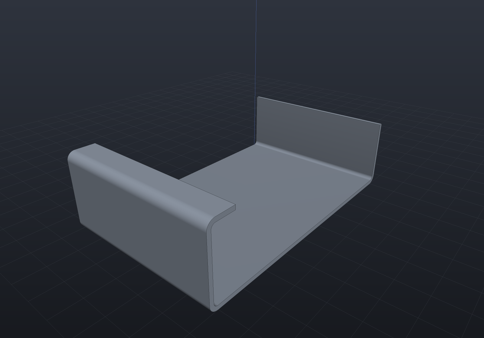
The bends are exact cylindrical bands welded straight into the parent’s loops — never booleans. A bend meets both the parent sheet and the flange wall tangentially, which is degenerate boolean input, and there is nothing to compute anyway: every face is a closed form. So the whole part is B-Rep Native.
var spec = new SheetMetalSpec(1.5, 1.5);var body = SheetMetalBody.Base(Sketch.Rectangle(60, 40), spec)    .WithFlange(SheetFlangeTarget.BaseEdge(1), 20);
var report = body.Solid.Explain(TargetRep.Brep);if (!report.IsConvertible) throw new Exception(report.ToString());
Partial flanges
Give a flange a startOffset and a width and it occupies part of the edge, leaving
the wall intact either side. A flange’s two ends are independent: each is either
flush with its edge’s own end — where the flange’s cross-section is spliced into the
neighbouring wall — or inset from it, where the flange gets a cap and the leftover
wall a stub. A flange running to one end of a plate is one of each, which is the
ordinary shop case and needs no special path.
var spec = new SheetMetalSpec(Thickness: 1.2, BendRadius: 1.2, KFactor: SheetMaterials.Aluminium);
var tabbed = SheetMetalBody    .Base(Sketch.Polygon([new(0, 0), new(120, 0), new(120, 50), new(0, 50)]), spec)    .WithFlange(SheetFlangeTarget.BaseEdge(1), length: 15, startOffset: 8, width: 14)    .WithFlange(SheetFlangeTarget.BaseEdge(1), length: 15, startOffset: 28, width: 14)    .WithFlange(SheetFlangeTarget.BaseEdge(3), length: 22, angleDegrees: 120);
var scene = new Scene();scene.Add(new Part("tabbed", tabbed.Solid) { Color = new PartColor(0.72f, 0.68f, 0.55f) });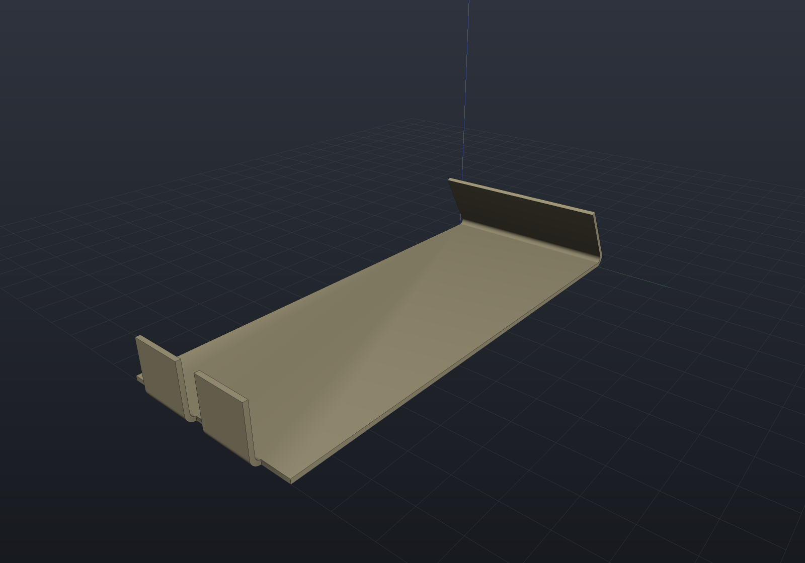
Bend reliefs
Where a flange stops short of its edge, the parent material beside the bend has to give
way — so a bend relief is notched into it. Give a flange a BendRelief and one is
cut at each inset end (a flush end has no parent material beside it to relieve).
A relief is a notch in the blank, not a cut in the folded body. It changes
BaseOutline — the base sketch with every relief cut into it — which is what the folded
sheet is extruded from and what the flat pattern starts from. So there is no boolean
and no second description: the same declaration produces both views, exactly as an edge
flange does. It also makes the geometry simpler, because between its two notches a
relieved flange runs the full width of the shortened wall, which is the ordinary flush
case.
var spec = new SheetMetalSpec(Thickness: 2, BendRadius: 2, KFactor: SheetMaterials.MildSteel);
var bracket = SheetMetalBody    .Base(Sketch.Polygon([new(0, 0), new(110, 0), new(110, 60), new(0, 60)]), spec)    .WithFlange(        SheetFlangeTarget.BaseEdge(1), length: 24, startOffset: 14, width: 32,        relief: BendRelief.Obround(width: 5, depth: 10))    .WithFlange(        SheetFlangeTarget.BaseEdge(3), length: 18, startOffset: 20, width: 24,        relief: BendRelief.Rectangular(width: 4, depth: 8));
var scene = new Scene();scene.Add(new Part("relieved", bracket.Solid) { Color = new PartColor(0.62f, 0.66f, 0.72f) });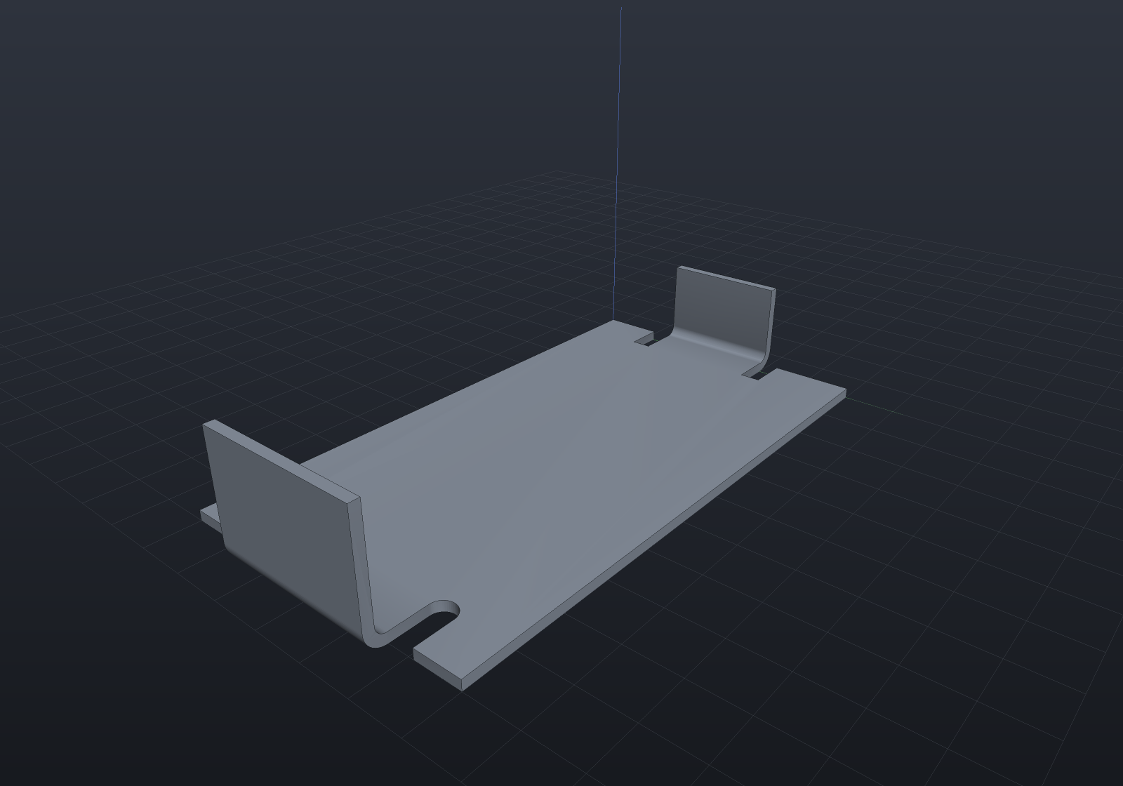
BendRelief.Rectangular(width, depth) | Two sides and a flat bottom. |
BendRelief.Obround(width, depth) | Rounded at the bottom with a semicircle of half the width — the fatigue-friendly form, since a square inside corner is a stress raiser. Depth reaches the deepest point, so it can never be less than half the width. |
Both dimensions default: width to one sheet thickness, depth to R + T, which
takes the notch past the bend’s own tangent region. A tear relief is deliberately
absent from the vocabulary — it is what happens when no relief is cut at all, and the
shape the material tears into belongs to the press, not to the geometry.
On a flange’s tip the same declaration means the same thing, by a different route. A flange’s wall is built from four corners rather than from a sketch, so there is no outline to notch: the notches travel with the parent flange’s own construction instead, which is why a parent has to know about its children’s reliefs before it is built. What they buy is identical — between them the child runs the full width of a tip face that is still four-sided, so it reaches the surgery as an ordinary flush flange, and the same two exact statements hold (the blank loses the notches’ own closed-form area, the folded body that times the thickness, and the folded-versus-flat discrepancy does not move).
var spec = new SheetMetalSpec(Thickness: 1.5, BendRadius: 1.5, KFactor: SheetMaterials.MildSteel);
var bracket = SheetMetalBody    .Base(Sketch.Polygon([new(0, 0), new(90, 0), new(90, 55), new(0, 55)]), spec)    .WithFlange(SheetFlangeTarget.BaseEdge(1), length: 28)    // A relief on the FLANGE's tip: the notches are cut into that flange's wall.    .WithFlange(        SheetFlangeTarget.FlangeTip(0), length: 16, startOffset: 14, width: 27,        relief: BendRelief.Obround(width: 4, depth: 7));
var scene = new Scene();scene.Add(new Part("bracket", bracket.Solid) { Color = new PartColor(0.66f, 0.70f, 0.74f) });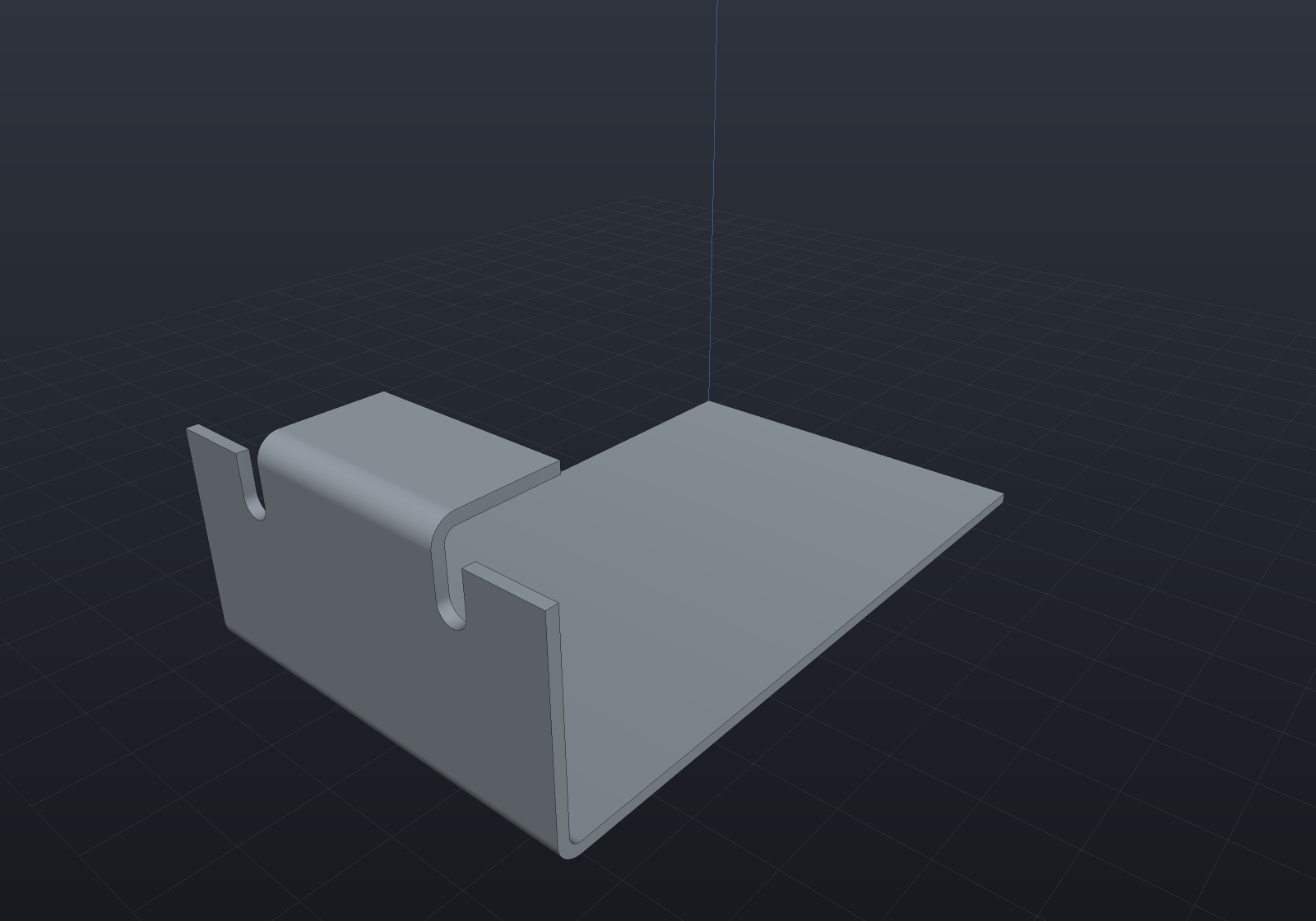
A notch that reaches past the far side of its parent — or into a hole in it — is refused, naming the point: on the base flange a notch is a detour in the outline, so one running out of the parent leaves a self-intersecting blank, and it does so silently (the signed area still reads base-minus-notches, and the extrusion still validates). On a flange tip the same refusal is one comparison, since the parent there is a rectangle.
Closed corners
Two flanges on adjacent edges are declared as one thing, because they are one
operation: WithCorner locates both bend lines before either is built and miters
them against each other, so the corner closes with no gap.
The miter is a closed form, not an intersection. Two bends of the same radius quoted
on the same face have axes that meet over the sheet’s corner, and two equal-radius
cylinders with intersecting axes meet in ellipses — so each band’s cut is an exact
Ellipse3d and nothing is traced. The two flanges’ cut chains are the same curves (the
configuration is symmetric under reflection in the miter plane, which swaps them), so
they are welded rather than butted: nothing lies in the miter plane at all.
var spec = new SheetMetalSpec(Thickness: 1.5, BendRadius: 2, KFactor: SheetMaterials.MildSteel);
var tray = SheetMetalBody    .Base(Sketch.Polygon([new(0, 0), new(90, 0), new(90, 60), new(0, 60)]), spec)    .WithCorner(SheetFlangeTarget.BaseEdge(1), SheetFlangeTarget.BaseEdge(2), length: 25)    // The other corner is left OPEN, the way a relieved one is: this flange stops short    // of it and a relief notches the blank beside the bend.    .WithFlange(        SheetFlangeTarget.BaseEdge(3), length: 25, startOffset: 6, width: 48,        relief: BendRelief.Obround());
var scene = new Scene();scene.Add(new Part("tray", tray.Solid) { Color = new PartColor(0.62f, 0.70f, 0.80f) });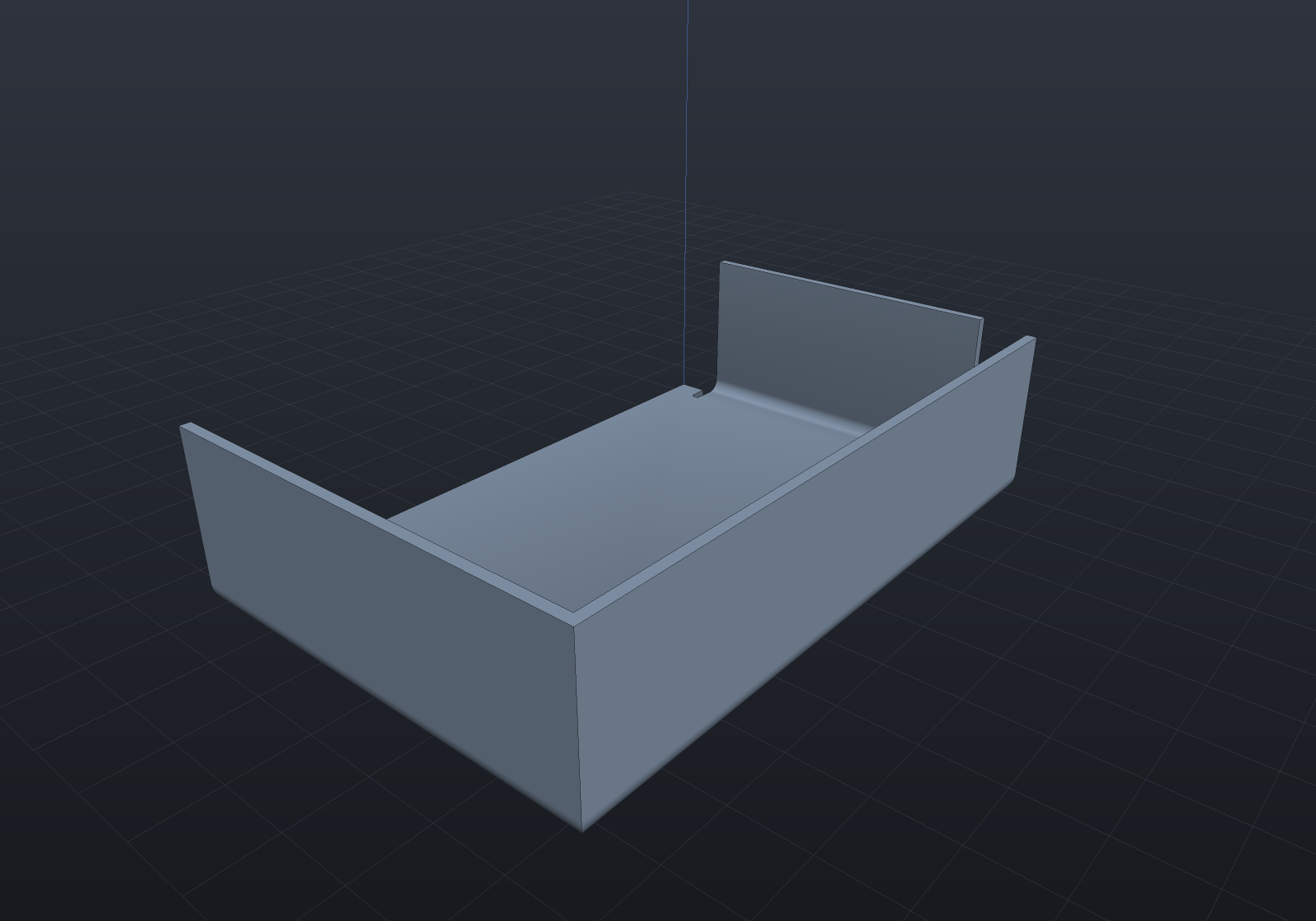
What a corner does to the volume identity is the price of sharing material, and it is
exact. Each flange’s material now runs to the miter plane rather than stopping at the
sheet’s corner, so the folded body gains the first moment of that flange’s own
cross-section about the corner line — ((R+T)³ − R³)/3 from the bend’s annular sector
plus T·L·(R + T/2) from the wall — while the blank is untouched. That the blank cannot
supply it is exactly what “an unrelieved corner shares material” means.
The pair must share one sheet corner and agree on radius, angle and length; anything else refuses by name. To leave the corner open instead, inset one flange and cut a bend relief.
Hems, jogs and curls
Each is two or more ordinary bends, so none of them is new geometry — what the API adds is the declaration and the arithmetic that turns a shop dimension into flange lengths.
A hem folds the edge back on itself as two bends the same way. It is deliberately
not one 180° fold: that has no geometry here at all (its outside setback
(R+T)·tan(θ/2) diverges) and a return leg flat against the sheet is coincident
boundary. The gap is 2R + L for an intermediate leg L, so a gap of 2R or less is a
closed hem and refuses by name — a tight hem is spelt with a small bend radius, which
is what flattening the material in the press means.
A jog is two equal and opposite bends, and its intermediate leg is closed form:
the perpendicular step is (2R + T)(1 − cos θ) + L·sin θ, so L = (offset − (2R + T)(1 − cos θ)) / sin θ. Below the minimum the refusal names the smallest offset that
radius and angle allow.
A curl is a chain of equal hits, and it is honestly polygonal: a rolled edge past 180° is one continuous band this bend model cannot spell, and a press makes one in successive hits anyway. The flat pattern, the bend table and the volume identity all describe exactly the part this builds.
var spec = new SheetMetalSpec(Thickness: 1.0, BendRadius: 1.0, KFactor: SheetMaterials.Aluminium);
var panel = SheetMetalBody    .Base(Sketch.Polygon([new(0, 0), new(110, 0), new(110, 45), new(0, 45)]), spec)    .WithHem(SheetFlangeTarget.BaseEdge(1), returnLength: 12, gap: 4)    .WithJog(SheetFlangeTarget.BaseEdge(3), offset: 8, runLength: 20);
var scene = new Scene();scene.Add(new Part("panel", panel.Solid) { Color = new PartColor(0.80f, 0.74f, 0.58f) });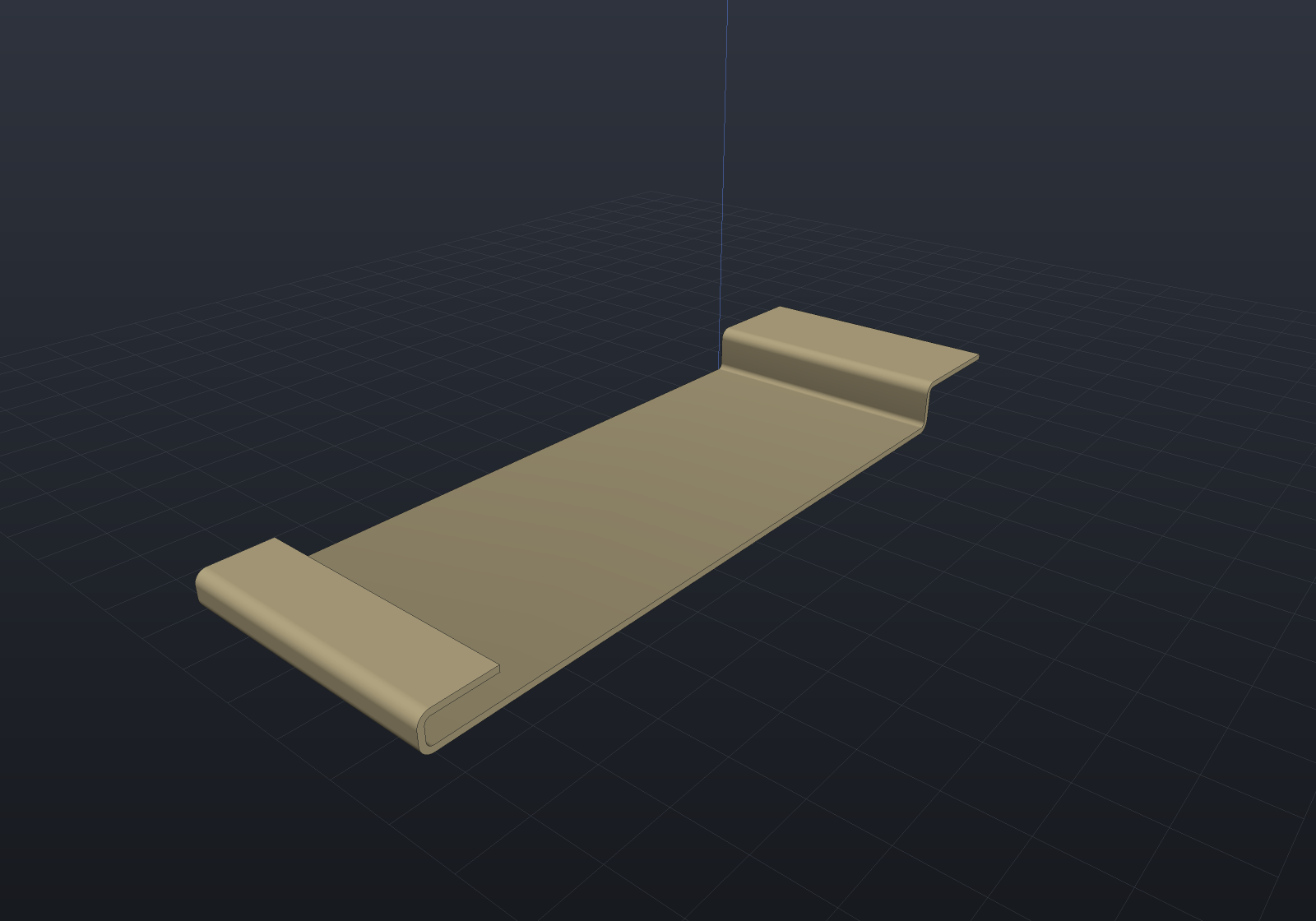
Cutouts on a flange
A flange’s wall can carry holes, declared in the flange’s own local coordinates —
x along the bend line from the flange’s start, y out from the bend’s tangent line.
One declaration reaches both views, exactly as a bend relief does: the folded wall is
punched and the blank gains the same holes through the flange’s rigid flat frame.
var spec = new SheetMetalSpec(Thickness: 1.5, BendRadius: 2, KFactor: SheetMaterials.MildSteel);
var bracket = SheetMetalBody    .Base(Sketch.Polygon([new(0, 0), new(100, 0), new(100, 60), new(0, 60)]), spec)    .WithFlange(SheetFlangeTarget.BaseEdge(1), length: 30, cutouts:    [        Sketch.Circle(4).Placed((15, 12), (1, 0)),        Sketch.Circle(4).Placed((45, 12), (1, 0)),        Sketch.Slot(14, 6).Placed((30, 22), (1, 0)),    ]);
var scene = new Scene();scene.Add(new Part("bracket", bracket.Solid) { Color = new PartColor(0.68f, 0.72f, 0.60f) });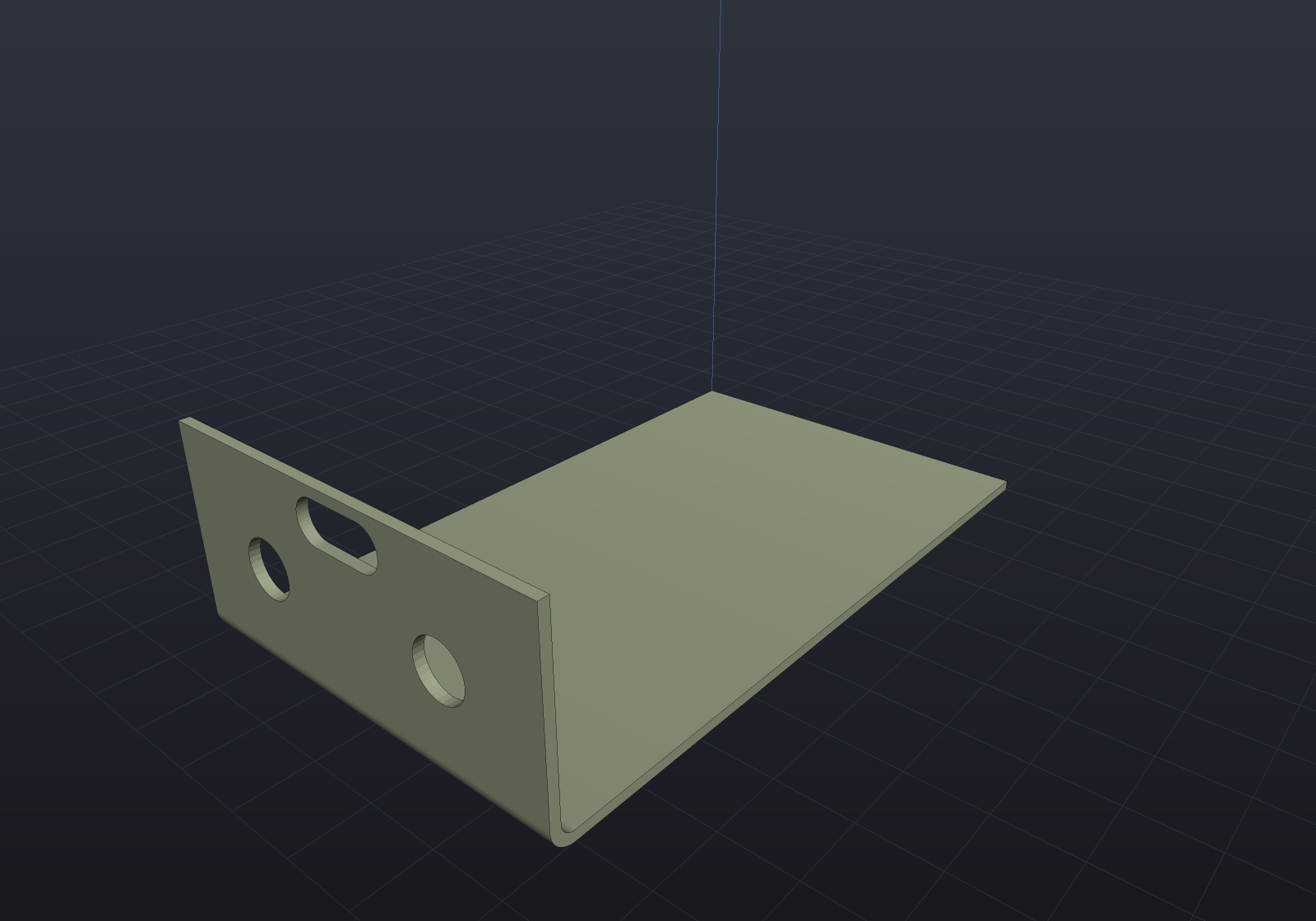
Slots that cross the bend line
A cutout may run out of the wall and down into the bend, and where it does it must be a rectangle aligned with the bend line. That is the complete exact tier rather than a budget: bending is an isometry of the sheet, so a straight cut running along the bend line stays straight (it becomes a ruling of the cylinder) and one running across it becomes a circular arc — and the wall each sweeps through the thickness is a plane. A cut at any other angle wraps to a helix, and an arc in the blank wraps to nothing with a closed form at all; both are refused by name rather than fitted.
var spec = new SheetMetalSpec(Thickness: 1.5, BendRadius: 2, KFactor: SheetMaterials.MildSteel);
// The bend zone occupies y from -BA to 0 in the flange's own local frame, so a negative// y is inside the bend. BA = angle x (R + K x T).double allowance = SheetMetalSpec.BendAllowance(Math.PI / 2, 2, 1.5, SheetMaterials.MildSteel);
Sketch Slot(double x0, double x1, double y0, double y1) =>    Sketch.Polygon([new(x0, y0), new(x1, y0), new(x1, y1), new(x0, y1)]);
var duct = SheetMetalBody    .Base(Sketch.Polygon([new(0, 0), new(100, 0), new(100, 60), new(0, 60)]), spec)    .WithFlange(SheetFlangeTarget.BaseEdge(1), length: 30, cutouts:    [        Slot(10, 20, -allowance * 0.6, 14),        Slot(28, 38, -allowance * 0.6, 14),        Slot(46, 56, -allowance * 0.6, 14),    ]);
var scene = new Scene();scene.Add(new Part("duct", duct.Solid) { Color = new PartColor(0.70f, 0.66f, 0.60f) });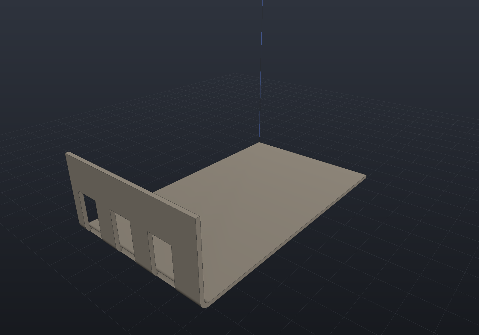
Each slot splits both bend bands into three — the two full-height stretches either side and a short one running under it, all ordinary full-domain bands of an arc — and notches both wall faces. Nothing here is a trimmed face and nothing is a boolean.
What a crossing slot costs is the K-factor’s independence from the folded shape, and
it cannot be otherwise: a cutout is declared flat (it is punched in the blank and then
bent, which is why holes near a bend deform), and the only map from the blank to the band
is the neutral-axis map, which K parameterizes. So the angle a slot bottoms out at is
resolved where K lives, and SheetBendSection still carries none.
The identity follows exactly, and it is the same formula the bend itself obeys restricted to the angle the slot takes away — a crossing slot removes a slice of the very discrepancy the K-factor owns:
blank loses w x (y1 - y0) x Tfolded loses w x (y1 x T + (theta - phi0) x T x (R + T/2))difference w x (theta - phi0) x T^2 x (0.5 - K)A slot that runs all the way through the bend into the parent is refused: that would notch the parent’s own faces, which is a change to the parent rather than to this flange. One that floats wholly inside the band is refused too — it would leave the band a trimmed face with a hole in it, a different construction.
Louvres
A louvre is a tab lanced out of the middle of a face and formed up, leaving a vent. It is not an edge flange and needed its own declaration for a structural reason: an edge flange’s bend line is an edge of the sheet and its material grows outboard of the blank, while a louvre’s bend line is interior to a face and its material comes from the sheet itself.
var spec = new SheetMetalSpec(Thickness: 1.2, BendRadius: 1.2, KFactor: SheetMaterials.MildSteel);
var panel = SheetMetalBody    .Base(Sketch.Polygon([new(0, 0), new(90, 0), new(90, 60), new(0, 60)]), spec);
// Three rows of vents, all opening the same way.for (int row = 0; row < 3; row++){    for (int i = 0; i < 3; i++)    {        panel = panel.WithLouvre(new SheetLouvre(            Origin: new Vector2d(20 + row * 25, 15 + i * 15),            Opening: new Vector2d(1, 0),            Width: 11, LanceLength: 8, AngleDegrees: 40));    }}
var scene = new Scene();scene.Add(new Part("panel", panel.Solid) { Color = new PartColor(0.72f, 0.70f, 0.66f) });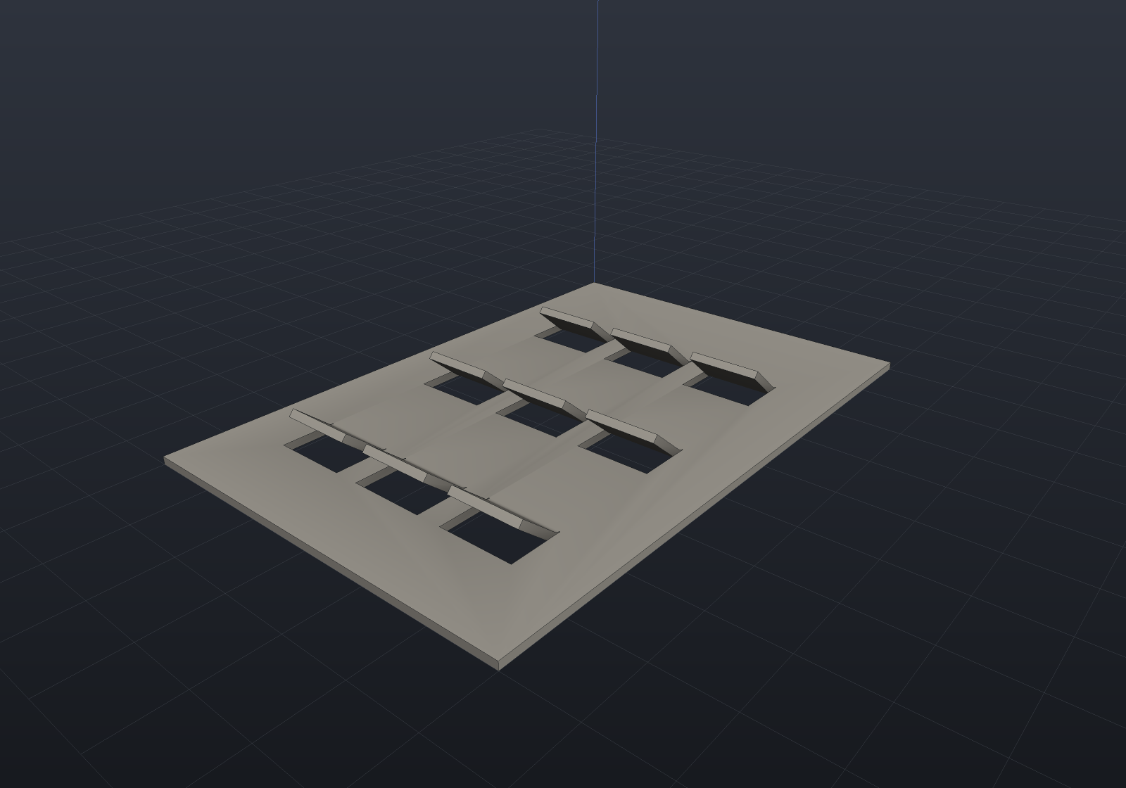
A lance has a width, and that is a theorem rather than a modelling choice. A cut of
zero width would leave the tab’s own side face coincident with the wall of the opening it
came out of, everywhere the bend band still lies inside that opening — two coplanar faces
with opposite normals touching over an area, which is not a manifold solid. So
Clearance is the width of the cut (a punch’s die clearance, a laser’s kerf), it is
strictly positive, and zero is refused by name.
That settles what each view loses, and the two answers are different on purpose:
| View | What it loses | Why |
|---|---|---|
The blank (BaseOutline, Unfold()) | Only the kerf — a U-shaped slot of area c·(W + 2L + 2c) | A lance separates material; it does not remove the tab. |
The folded parent (FoldedOutline) | The whole opening, (W + 2c) × (L + c) | The tab has left the plane, and comes back as its own flange. |
So the volume identity is untouched, and independent of the clearance: the kerf
leaves both views identically, the parent’s loss of W·L·T is returned by the tab as
W·θ·T·(R + T/2) + W·(L − BA)·T, and what is left is exactly W·θ·T²·(0.5 − K) — one
more term of the same sum an ordinary bend contributes.
One convention differs from every other length here, and it is stated on the type: a
louvre’s LanceLength is measured flat, along the blank from the bend line, because
the lance is a cut in the blank and its length is what the laser cuts — where a flange’s
Length is measured from the outer virtual sharp, which is how a drawing dimensions a
folded leg.
Refused by name: a zero-width lance, a lance running off the sheet or into a hole, two overlapping louvres, a lance shorter than its own bend allowance, and a tab so shallow it would swing back into the material beyond its own opening (a shallow tab reaches further out than the flat material it came from, by the thickness the bend swings it through).
The flat pattern
Unfold() is bookkeeping, not geometry re-derivation: it walks the flange tree,
gives each bend its allowance, and splices a rectangle into the blank outline. Holes
drawn in the base sketch keep their position, because the flat pattern’s coordinates
are the base sketch’s.
The result carries the blank and one FlatBendLine per bend — both tangent lines of
the bend zone, the angle, the radius, the allowance and whether the fold is up or
down.
var spec = new SheetMetalSpec(Thickness: 1.5, BendRadius: 1.5, KFactor: SheetMaterials.MildSteel);
var chassis = SheetMetalBody    .Base(        Sketch.Polygon([new(0, 0), new(120, 0), new(120, 70), new(0, 70)])            .WithHole(Sketch.Circle(new Vector2d(30, 35), 6))            .WithHole(Sketch.Circle(new Vector2d(90, 35), 6)),        spec)    .WithFlange(SheetFlangeTarget.BaseEdge(1), length: 22)    .WithFlange(SheetFlangeTarget.BaseEdge(3), length: 22)    .WithFlange(SheetFlangeTarget.BaseEdge(0), length: 14, startOffset: 15, width: 90);
var svg = chassis.Unfold().ToDrawing().ToSvg();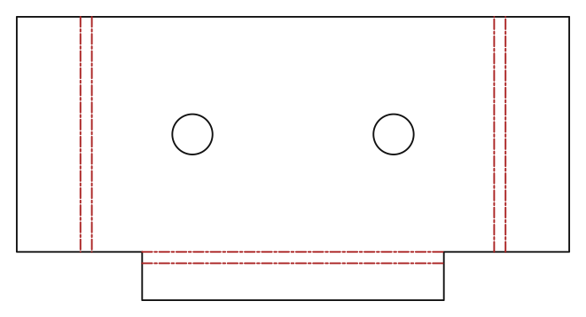
Reliefs appear in the blank as the notches they are, because the blank is the outline they were cut into:
var spec = new SheetMetalSpec(Thickness: 2, BendRadius: 2, KFactor: SheetMaterials.MildSteel);
var svg = SheetMetalBody    .Base(Sketch.Polygon([new(0, 0), new(110, 0), new(110, 60), new(0, 60)]), spec)    .WithFlange(        SheetFlangeTarget.BaseEdge(1), length: 24, startOffset: 14, width: 32,        relief: BendRelief.Obround(width: 5, depth: 10))    .WithFlange(        SheetFlangeTarget.BaseEdge(3), length: 18, startOffset: 20, width: 24,        relief: BendRelief.Rectangular(width: 4, depth: 8))    .Unfold()    .ToDrawing()    .ToSvg();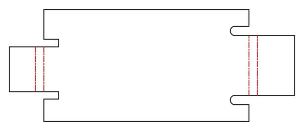
The bend table
BendTable() is the press brake’s setup sheet: one row per bend in declaration order,
with the length of the bend line, the angle, which way it folds, the inside radius and
the allowance. Every column is read off the same FlatBendLine records the drawing’s
bend zones are drawn from, so the table and the picture cannot disagree.
var spec = new SheetMetalSpec(1.5, 1.5);var body = SheetMetalBody.Base(Sketch.Rectangle(80, 50), spec)    .WithFlange(SheetFlangeTarget.BaseEdge(1), 25)    .WithFlange(SheetFlangeTarget.BaseEdge(3), 18, direction: SheetBendDirection.Down);
Console.WriteLine(body.Unfold().BendTable());// BEND  LENGTH   ANGLE  DIR   RADIUS  ALLOWANCE//    1  50.000    90.0  UP     1.500      3.394//    2  50.000    90.0  DOWN   1.500      3.394var rows = body.Unfold().BendTable().Split('\n', StringSplitOptions.RemoveEmptyEntries);if (rows.Length != 3) throw new Exception("a header and one row per bend");
Out to the shop
ToDxf() writes what a laser cutter wants: the blank on a CUT layer, the bend
zones’ tangent lines on a BEND layer given the CENTER line type, so a reader that
honours the LTYPE table shows them chain-dashed rather than as cuts.
var spec = new SheetMetalSpec(1.5, 1.5);var body = SheetMetalBody.Base(Sketch.Rectangle(80, 50), spec)    .WithFlange(SheetFlangeTarget.BaseEdge(1), 25);
var flat = body.Unfold();flat.ToDxf().SaveFile(Path.Combine(Scratch, "bracket-flat.dxf"));
// One outline plus two bend-zone lines.var reloaded = DxfDocument.LoadFile(Path.Combine(Scratch, "bracket-flat.dxf"));if (reloaded.ToSketches("CUT").Count != 1) throw new Exception("expected one blank outline");if (reloaded.Entities.Count(e => e.Layer == "BEND") != 2) throw new Exception("expected two bend lines");
The oracle: folded volume versus flat volume
The bend model has a built-in test, and it is sharper than “the two volumes are about
equal”. A bend’s folded material is an annular sector — θ·T·(R + T/2) per unit width
— while the blank spends BA·T = θ·T·(R + K·T) on it. So:
- at K = 0.5 the folded body and the flat blank have exactly the same volume;
- at any other K they differ by
Σ width·θ·T²·(0.5 − K), a closed form.
That is the K-factor doing its job (a lower K means the neutral axis sits nearer the inside, so the blank is shorter), not an error — and pinning it in both direction and magnitude is what makes it a real check.
var coined = new SheetMetalSpec(1.5, 2.0, SheetMaterials.Coined);   // K = 0.5var body = SheetMetalBody.Base(Sketch.Polygon([new(0, 0), new(80, 0), new(80, 50), new(0, 50)]), coined)    .WithFlange(SheetFlangeTarget.BaseEdge(1), 25);
double folded = BrepMassProperties.Compute(body.Solid.ToBrep()).Volume;double flat = body.Unfold().Volume;if (Math.Abs(folded / flat - 1) > 1e-6) throw new Exception($"folded {folded:g10} vs flat {flat:g10}");
// And away from 0.5 the gap is exactly the formula's.var steel = new SheetMetalSpec(1.5, 2.0, SheetMaterials.MildSteel);var other = SheetMetalBody.Base(Sketch.Polygon([new(0, 0), new(80, 0), new(80, 50), new(0, 50)]), steel)    .WithFlange(SheetFlangeTarget.BaseEdge(1), 25);double gap = BrepMassProperties.Compute(other.Solid.ToBrep()).Volume - other.Unfold().Volume;double predicted = 50 * (Math.PI / 2) * 1.5 * 1.5 * (0.5 - SheetMaterials.MildSteel);if (Math.Abs(gap - predicted) > 1e-4) throw new Exception($"gap {gap:g10}, predicted {predicted:g10}");
A bend relief leaves that discrepancy exactly where it was, which is what makes the oracle worth extending rather than replacing: a relief takes the same material out of the folded body and out of the blank, so it contributes nothing to the gap. A relief that notched only one of the two views — the failure a “the volumes are about equal” test waves through — shows up here as a gap wrong by the whole notch volume.
var spec = new SheetMetalSpec(1.5, 2.0, SheetMaterials.SoftAluminium);var body = SheetMetalBody.Base(Sketch.Polygon([new(0, 0), new(80, 0), new(80, 50), new(0, 50)]), spec)    .WithFlange(SheetFlangeTarget.BaseEdge(1), 25, startOffset: 10, width: 30,        relief: BendRelief.Obround(width: 3, depth: 4));
double gap = BrepMassProperties.Compute(body.Solid.ToBrep()).Volume - body.Unfold().Volume;double predicted = 30 * (Math.PI / 2) * 1.5 * 1.5 * (0.5 - SheetMaterials.SoftAluminium);if (Math.Abs(gap - predicted) > 1e-4) throw new Exception($"gap {gap:g10}, predicted {predicted:g10}");
As a parametric feature
BaseFlangeFeature and EdgeFlangeFeature put sheet metal in the
feature history, so a sheet part regenerates, caches, suppresses and
saves like any other. The bend line is named with an
EdgeSetRef resolved against the regenerated body — the
topological-naming story — and mapped back into the flange tree, so “the flange on
THAT edge” survives an edit upstream of it.
var history = new FeatureHistory();history.Add(new BaseFlangeFeature(Sketch.Polygon([new(0, 0), new(80, 0), new(80, 50), new(0, 50)])){    Thickness = 1.5,    BendRadius = 2.0,    KFactor = SheetMaterials.MildSteel,});history.Add(new EdgeFlangeFeature{    Length = 25,    Edge = SheetMetalFeatures.EdgeBetween((80, 0, 1.5), (80, 50, 1.5)),    // A relief is a parameter like any other, and an OPTIONAL one: null cuts none. It    // can be the geometry's own nullable enum because a [Param] dropdown now offers a    // "(none)" row for one -- the rule is that a parameter whose editor can express    // absence takes the nullable type.    Relief = null,});
var result = history.Regenerate();if (!result.Succeeded) throw new Exception(result.ToString());
// The flat pattern comes off the regenerated body, not off a second model.var flat = SheetMetalFeatures.TryUnfold(result.Body)!;if (flat.Bends.Count != 1) throw new Exception("expected one bend");
What is not supported
Refused by name, rather than approximated:
| Not supported | Why |
|---|---|
| Bends along non-straight edges | Not a gap but a theorem. Folding a sheet along a curve is not an isometry of the sheet, so no flat blank produces it: along a circular bend line the band is a torus segment, whose Gaussian curvature is non-zero everywhere a flat sheet’s is zero. The material would have to stretch or shrink, which is forming rather than bending and has no bend allowance. Approximate it as a chain of straight bends, or model it as forming and accept that its blank is not derivable. |
| Two flanges sharing a stretch of one edge | Two bends cannot occupy the same material — and a relief counts as part of the stretch its flange occupies. |
| Flanges on a flange’s side edges | Only the tip: a side flange is a corner interaction. |
| A cutout crossing a bend line that is not an aligned rectangle | Not a budget but the complete exact tier: a straight cut at any other angle wraps to a helix, and an arc in the blank wraps to nothing with a closed form. |
| A cutout running through the bend into the parent, or floating wholly inside it | The first notches the parent’s faces, the second leaves the band a trimmed face with a hole in it. Both are different constructions rather than harder versions of this one. |
| A zero-width lance | Not a limit but a theorem: the tab’s side face would be coincident with the wall of the opening it came out of, over the whole stretch where the bend band still lies inside it. State the die clearance or the kerf. |
| Tear reliefs, spring-back compensation | Both belong to the press rather than to the geometry — a tear relief is what happens when no relief is cut. |
Every one of these throws with a message naming what it hit and what to do instead.
Multi-body sheets and welded assemblies
A sheet part is one flange tree and one blank, by design rather than by omission. A
weldment of sheet metal is several parts — each with its own base flange, its own tree
and its own blank — held together by an Assembly: the BOM counts them, mates position
them, and SheetMetalFeatures.UnfoldAll cuts them. Folding several bodies into one
SheetMetalBody would make FlatPattern mean two things at once, and a laser cuts one
blank per body either way.
What is not a sheet part is equally deliberate: a boolean of two sheet solids is a solid, not a sheet part — a union node carries no flange tree, so it has no blank. Weld the parts in an assembly, not in the geometry.
var spec = new SheetMetalSpec(Thickness: 1.5, BendRadius: 2, KFactor: SheetMaterials.MildSteel);
SheetMetalBody Panel(double x, double y) => SheetMetalBody    .Base(Sketch.Polygon([new(0, 0), new(x, 0), new(x, y), new(0, y)]), spec)    .WithFlange(SheetFlangeTarget.BaseEdge(1), length: 18);
var chassis = new Assembly("chassis");chassis.Add(new Part("side", Panel(60, 40).Solid));chassis.Add(new Part("lid", Panel(60, 25).Solid), Frame3d.FromXY((0, 60, 0), (1, 0, 0), (0, 1, 0)));
var scene = new Scene();scene.AddTab("Model").Add(chassis);
// One blank per body, each once, however deeply nested.var blanks = SheetMetalFeatures.UnfoldAll(scene);if (blanks.Count != 2) throw new Exception("expected one blank per body");
Out to the shop without a script
--flat writes every sheet part’s flat pattern from a model program, and the viewer’s
Flat button does the same for the selected part (bend table in a window, DXF beside
it, path in the status bar).
dotnet run --project mypart -- --flat blank.dxf # the laser's outline plus bend linesdotnet run --project mypart -- --flat blank.svg # the same, to look atdotnet run --project mypart -- --flat setup.txt # the press brake's bend tableIt is its own verb rather than an --export extension because “this scene as DXF” is
genuinely ambiguous — a drawing sheet, a section and a flat pattern are three different
2D answers to it. A scene with several sheet parts writes one file each,
<stem>-<part><ext>; each has its own blank, so one path cannot serve them.
Mirrored placements
A mirrored sheet part is re-declared, not re-placed: a flange tree is ordered and
quoted on named edges, so a reflection has to move the names. Shape.Mirror rebuilds
the tree the other way round — the base sketch reflected (which reverses its winding, so
a segment at index i of n lands at n − 1 − i), every flange’s span reversed along
its own edge, every cutout mirrored in its flange’s local x — and places it on a proper
frame. The reflection is taken in the sketch plane, so the sheet’s own +Z never moves
and SheetBendDirection keeps meaning one thing.