Topology optimisation
Every other solver here answers how does this part behave. This one answers where should
the material go: given a design space, a set of supports, a load and a volume budget,
TopologyOptimizer returns a density per element saying how much material each part of the
space is worth.
It minimises compliance — c = u'Ku, the work the load does, so the smallest compliance is
the stiffest structure — by SIMP (Solid Isotropic Material with Penalisation), which
interpolates the modulus as E(rho) = rho^p·E0. The exponent’s whole job is to make
half-dense material less than half as useful as solid material, so the answer tends toward
solid-or-void rather than settling into a uniform grey mush.
// The DESIGN SPACE: everywhere the material is allowed to be.var space = Shape.Box(60, 32, 5);var tets = TetMesher.Mesh(space.ToMesh(), new TetMeshOptions{    RefineQuality = true,    MaxElementSize = 5,       // deliberately coarse - this page is a picture, not a study});
var model = new StructuralModel(AnalysisMesh.Of(tets), Materials.Steel);model.Fix(Facets.OnPlane(new Vector3d(-30, 0, 0), Vector3d.UnitX));// The tip load on the BOTTOM of the free end rather than over the whole face. A load spread// over the whole section is a beam problem and the answer is a spar; a corner load has to be// carried diagonally, which is what makes the load PATH visible.model.Force(    Facets.And(        Facets.OnPlane(new Vector3d(30, 0, 0), Vector3d.UnitX),        Facets.InBox(new Aabb(new Vector3d(29, -17, -3), new Vector3d(31, -10, 3)))),    new Vector3d(0, 0, -2000));
var result = TopologyOptimizer.Minimize(model, new TopologyOptions{    VolumeFraction = 0.35,    // keep about a third of the box    FilterRadius = 4.0,       // the MINIMUM MEMBER SIZE, in millimetres - see below});
// A density field varies at ELEMENT scale, so it has to be shown on a mesh that resolves it.// The design space's OWN display mesh is an eight-vertex box, and colouring that interpolates// the entire answer across eight corners: the same picture came back reading 0.002 to 0.116// on a field whose true range is 0.001 to 1. The tet mesh's boundary is the mesh that// resolves it, and its vertices ARE analysis nodes, so every sample matches exactly.var skin = tets.BoundaryMesh(out _);var part = new Part("design space", Shape.From(skin));foreach (var field in result.SampleOnto(skin))    part.AddResult(field);part.FieldDisplay = new FieldDisplay{    Field = TopologyResult.FieldNames.Density,    ColorMap = FieldColorMap.Viridis,};
var scene = new Scene();scene.Add(part);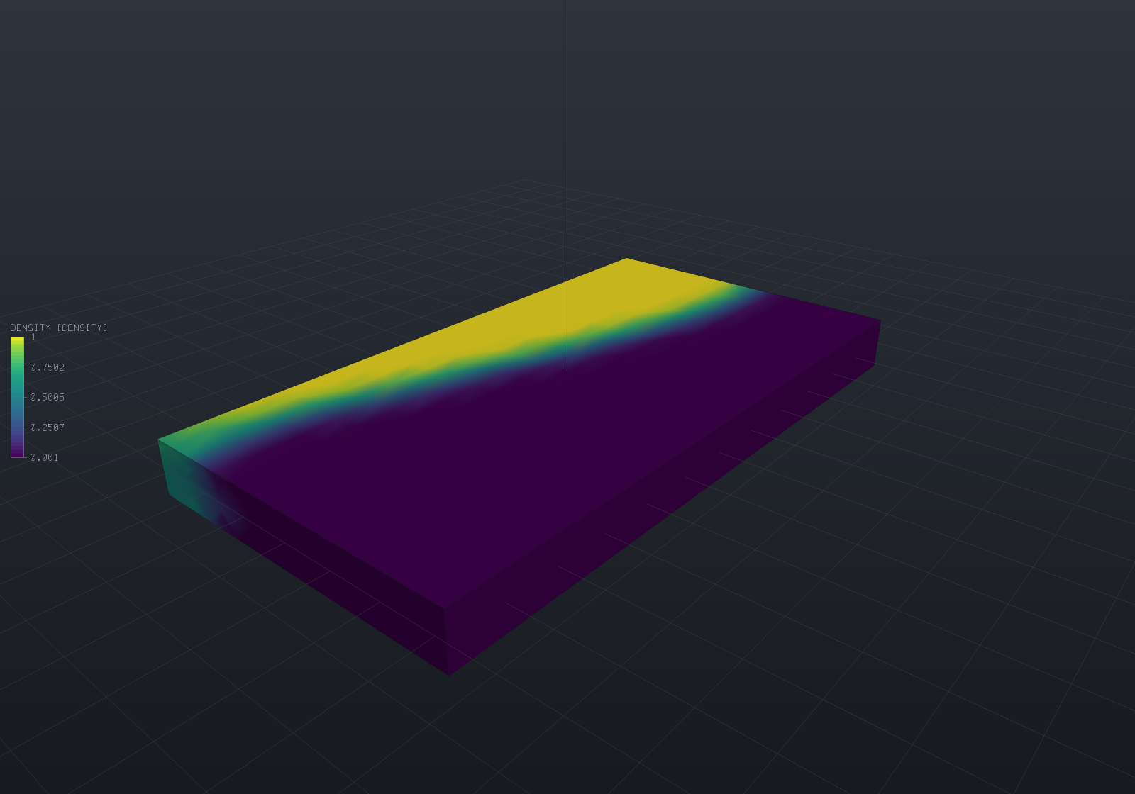
Yellow is material worth keeping, dark blue is material worth removing. The load path is a tapered arm running from the deep root to the loaded corner — deep where the bending moment is largest and slender where it is not — with the boundary between keep and remove sharp rather than smeared: this run comes out at a discreteness of 0.117, so the penalisation has very nearly decided.
Note that this is the field on the design space’s SKIN. That is the honest thing to show, because it is where the mesh has nodes; the members running through the interior are what the extraction below finds.
A recognisable result: the MBB beam
The cantilever above is a real answer, but the canonical topology-optimisation picture — the one the technique is famous for — is the MBB beam: a deep beam, simply supported at both ends and loaded straight down at the top centre. Its optimum is the iconic arch — a curved top chord in compression, a bottom tension tie, and a web of diagonals between — and it comes out symmetric, which is the one property that makes “it looks right” checkable (a wrong support breaks the symmetry, and the tests assert exactly that).
// Span along X, thickness along Y, DEPTH along Z — so the arch stands in the viewer's own// vertical and reads upright, with the load pointing straight down the world's -Z.var space = Shape.Box(80, 12, 24);        // span x thickness x depthvar tets = TetMesher.Mesh(space.ToMesh(), new TetMeshOptions{    RefineQuality = true,    MaxElementSize = 6,                   // ~7000 elements: a picture, not a study});
var model = new StructuralModel(AnalysisMesh.Of(tets), Materials.Steel);
// Simply supported: two bottom rollers carry the vertical reaction and pin the out-of-plane// slide; a single base-centre pin removes the last horizontal drift. The supports are// SYMMETRIC, so the arch is symmetric — and because a purely vertical load has zero horizontal// reaction, the structure still forms its own tension tie rather than leaning on a support.var bottom = Facets.FacingAlong(new Vector3d(0, 0, -1));model.Fix(Facets.And(bottom, Facets.InBox(    new Aabb(new Vector3d(-41, -7, -13), new Vector3d(-30, 7, -11)))), Dof.Y | Dof.Z);model.Fix(Facets.And(bottom, Facets.InBox(    new Aabb(new Vector3d(30, -7, -13), new Vector3d(41, 7, -11)))), Dof.Y | Dof.Z);model.Fix(Facets.And(bottom, Facets.InBox(    new Aabb(new Vector3d(-5, -7, -13), new Vector3d(5, 7, -11)))), Dof.X);model.Force(Facets.And(    Facets.FacingAlong(new Vector3d(0, 0, 1)),    Facets.InBox(new Aabb(new Vector3d(-5, -7, 11), new Vector3d(5, 7, 13)))),    new Vector3d(0, 0, -3000));
var result = TopologyOptimizer.Minimize(model, new TopologyOptions{    VolumeFraction = 0.5,                 // half the box, the classic MBB budget    FilterRadius = 4.0,                   // the MINIMUM MEMBER SIZE, in millimetres    Filter = TopologyFilter.Sensitivity,  // crisper, which is what the release below wants});
// The density on the design space's own SKIN, whose vertices ARE analysis nodes — the arch// reads on the front face because the structure is nearly prismatic through the thickness.var skin = tets.BoundaryMesh(out _);var part = new Part("MBB beam", Shape.From(skin));foreach (var field in result.SampleOnto(skin))    part.AddResult(field);part.FieldDisplay = new FieldDisplay{    Field = TopologyResult.FieldNames.Density,    ColorMap = FieldColorMap.Viridis,};
var scene = new Scene();scene.Add(part);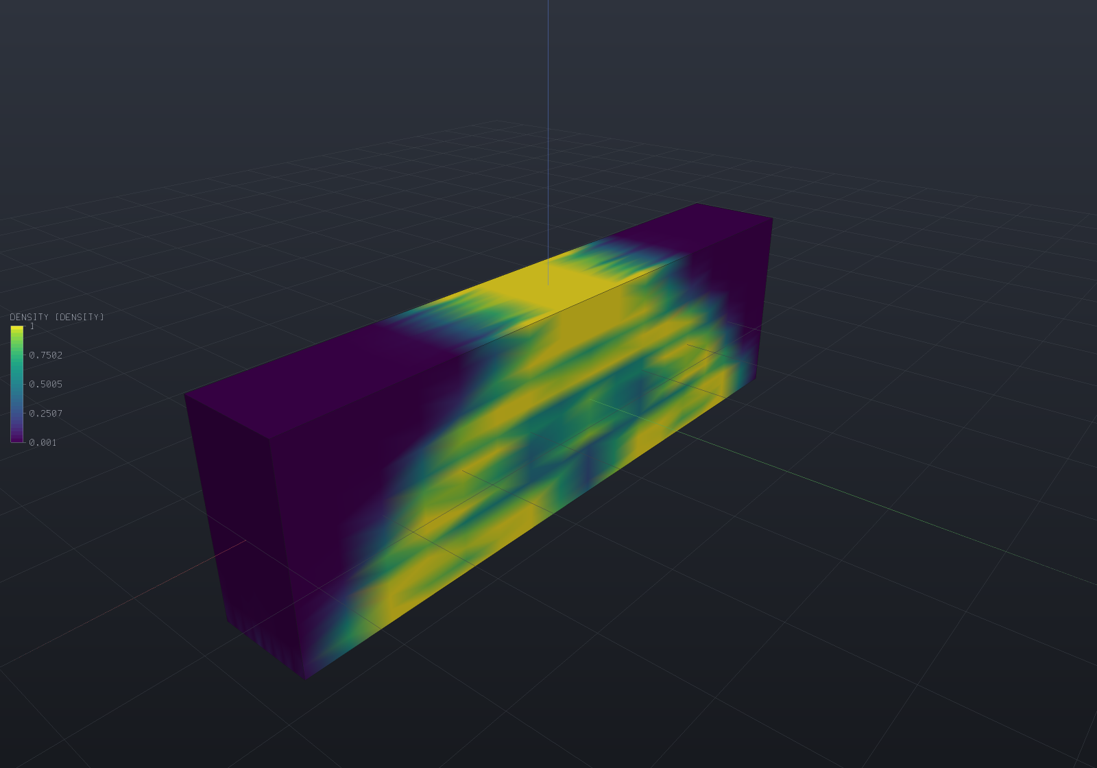
There is the arch: a hollow triangle under the load, a curved compression chord over the top, and a straight tension chord along the bottom between the supports. This run comes out at a discreteness of 0.232 — greyer than the cantilever, because the members are finer relative to the filter radius — so the threshold below moves the volume a little more, which is exactly why the release reports what it costs.
Releasing the result: smooth, remesh, export
The extracted iso-surface is the exact level set of the density field, and it is a poor
part: the field is thresholded on tetrahedra, so the boundary is stair-stepped at element
scale, and marching those tetrahedra produces triangles of every shape — the MBB’s raw surface
is 3 908 faces with 2 950 slivers and a smallest angle of essentially zero. Turning it into
something printable and re-meshable is two stages, and TopologyResult.Release runs both while
measuring what each one costs rather than hiding it behind a “cleaned up” result:
- Smoothing fairs the element-scale stair-steps (
LaplacianMeshSmoother, implicit fairing). It moves the surface, so it is no longer the exact iso-surface — and because a stair-step is material on the convex side of the mid-surface, fairing a thin structure shrinks it. The default is deliberately gentle (three steps at strength 0.1): a full step would melt the thin members (measured −42% of the volume), where the default costs about −6% and moves the farthest vertex 0.73 mm — a stated trade, not a silent one. - Remeshing re-triangulates the faired surface to a uniform edge length (
Remesher, projecting onto the smoothed mesh so it redistributes vertices without moving the surface — it stays within2e-14of it). This is the stage that makes the part usable: the sliver count drops 2 950 → 73 and the mean smallest-angle rises 21° → 48°, while the volume barely changes (−2%).
The order is smooth-then-remesh on purpose: fair the surface first, then redistribute vertices onto the faired surface. Doing it the other way round would remesh the stair-steps and then have to fair the uniform result, fighting the resolution the remesh just established.
var space = Shape.Box(80, 12, 24);        // span x thickness x depth (the arch stands in Z)var tets = TetMesher.Mesh(space.ToMesh(), new TetMeshOptions{    RefineQuality = true,    MaxElementSize = 6,});var model = new StructuralModel(AnalysisMesh.Of(tets), Materials.Steel);var bottom = Facets.FacingAlong(new Vector3d(0, 0, -1));model.Fix(Facets.And(bottom, Facets.InBox(    new Aabb(new Vector3d(-41, -7, -13), new Vector3d(-30, 7, -11)))), Dof.Y | Dof.Z);model.Fix(Facets.And(bottom, Facets.InBox(    new Aabb(new Vector3d(30, -7, -13), new Vector3d(41, 7, -11)))), Dof.Y | Dof.Z);model.Fix(Facets.And(bottom, Facets.InBox(    new Aabb(new Vector3d(-5, -7, -13), new Vector3d(5, 7, -11)))), Dof.X);model.Force(Facets.And(    Facets.FacingAlong(new Vector3d(0, 0, 1)),    Facets.InBox(new Aabb(new Vector3d(-5, -7, 11), new Vector3d(5, 7, 13)))),    new Vector3d(0, 0, -3000));var result = TopologyOptimizer.Minimize(model, new TopologyOptions{    VolumeFraction = 0.5, FilterRadius = 4.0, Filter = TopologyFilter.Sensitivity,});
// Extract, fair, remesh — the whole account of what each stage cost comes back as a value.var released = result.Release();          // TopologyReleaseStage.Remeshed by defaultConsole.WriteLine(released.ToText());//   iso-surface   vol 11994.2 (52.06%), 3908 faces, 1 component(s), ... 2950 slivers//   smoothed      vol 11280.3 (delta -6.0%), moved max 0.7326 / mean 0.232//   remeshed      vol 11046.0 (delta -2.1%), edge target 1.892, 3422 faces ...//                 slivers 2950 -> 73, stays within 1.9E-14 of the faired surface
// A HalfEdgeMesh crosses back into the modelling graph in one call — from there the released// part flows through --export (STL / 3MF / OBJ) and EngrCad.Show unchanged.var solid = Shape.From(released.Mesh);
// Export to STL and verify the round trip by signed-tetrahedral volume: writing then reading// the binary file and summing tetra volumes catches a wrong winding (the sign flips) or a hole// (it does not close). The delivered part is Validate-clean and its STL round-trips to float32.var path = Path.Combine(Scratch, "mbb.stl");StlWriter.WriteFile(released.Mesh, path);var readback = StlReader.ReadFile(path).RequireMesh();double roundTrip = MeshMassProperties.Compute(readback).Volume;if (!readback.IsClosed || Math.Abs(roundTrip - released.FinalVolume) / released.FinalVolume > 1e-5)    throw new Exception($"STL round trip failed: {roundTrip} vs {released.FinalVolume}");
var scene = new Scene();scene.Add(new Part("MBB beam", solid));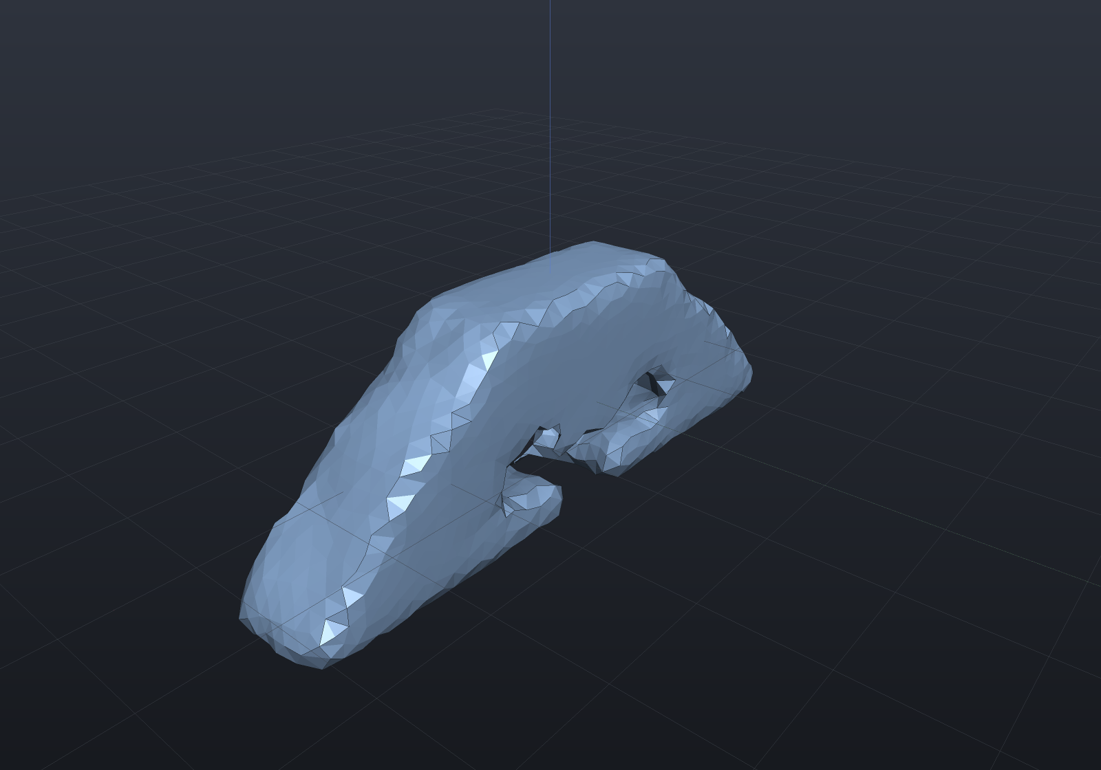
That is a printable part: a closed, Validate-clean, uniformly-triangulated solid that came
out of the optimiser as a density field. Two things it reports rather than hides. The delivered
volume is 47.9% of the design space against the 50% the optimiser was constrained to —
the threshold overshot to 52%, and fairing brought it back under — so the two stage deltas add
up to exactly the difference between the iso-surface and the deliverable, an identity a caller
can read off. And extraction keeps every tetrahedron above the threshold, so a disconnected
island survives as its own component (ReleasedTopology.ComponentCount) rather than being
silently deleted; a neck one element thick passes through as a valid manifold, though a
hair-thin one can pinch under fairing — a property of the threshold, not the release, so lower
the threshold or coarsen the filter if a member is meant to survive.
The three stages are honestly-different outputs, each reachable on its own
(TopologyReleaseStage.IsoSurface / Smoothed / Remeshed) with its own measured cost — the
same spirit as Shape.Remeshed being a graph node with an honest Explain rather than a hidden
rendering knob. (Release lives on TopologyResult and returns a HalfEdgeMesh, not a Shape,
because EngrCAD.Fea is a leaf that cannot see the modelling layer — Shape.From(released.Mesh)
is the one line that crosses back.)
Which optimiser: this or a design study?
Both search, and they are complements rather than competitors. The rule is short:
DesignStudy | TopologyOptimizer | |
|---|---|---|
| variables | a handful of [Param] values | one density per element — thousands |
| gradients | impossible, so derivative-free | mandatory, and free |
| what changes | dimensions of a shape you drew | which shape there is |
| use it to | size a part | find out what to draw |
The gradient row is the whole story. A design study is derivative-free because a parameter change can alter topology — a hole breaks through, a fillet stops fitting — and the two sides of such a step are different solids, so a finite difference across it is meaningless rather than merely noisy. Here the topology changing is the answer, and with one variable per element no derivative-free method reaches the dimension at all.
What makes the gradient free is that compliance is self-adjoint: with E(rho) = rho^p·E0
and a load that does not depend on the design,
dc/drho_e = -p·rho_e^(p-1)·(u_e' k0 u_e)and u_e' k0 u_e is the element strain energy — a quantity the solve has already produced. No
adjoint system, no second factorization. Every refusal below exists to protect that property.
The filter is not optional
Unfiltered SIMP fails in two ways at once, and neither is a tolerance question.
It checkerboards. Alternating solid and void elements is an artefact: that pattern overestimates its own stiffness in a displacement-based element, so the optimiser finds it and exploits it. Measured on the fixture in the tests, an unfiltered run leaves each element 0.555 away from the mean of its face neighbours against 0.020 filtered — 28× — and reports a compliance 37% lower for the same volume. A lower compliance that is not a better structure is exactly the failure a picture cannot show you.
And it is mesh-dependent: refining gives a different, finer truss forever rather than converging on one. Measured over three meshes at a fixed radius, the structure moves 0.137 then 0.068 between refinement levels unfiltered against 0.014 and 0.014 with a density filter — an order of magnitude.
A filter of radius r_min fixes both, and since it is also what sets the smallest member the
answer can contain, r_min is an engineering input rather than a numerical knob: it is the
thinnest wall your printer holds, or the diameter of your cutter. It is stated in model units,
it has no default, and if you find yourself turning it until the picture looks right then you
are choosing a manufacturing constraint by eye.
Two filters are offered and the difference matters:
TopologyFilter.Density(the default) convolves the design variable into a physical density, so the problem being solved is a genuine optimisation problem in the design variables and the reported sensitivity is its exact gradient — which is what lets the tests check it against a finite difference.TopologyFilter.Sensitivity(Sigmund 1997, the one the 99-line paper uses) smooths the sensitivity instead and leaves the densities alone. It converges much faster (22 iterations against 89 on the same fixture) and comes out crisper, but the filtered sensitivity is not the gradient of anything, so it is a heuristic and is documented as one.TopologyFilter.Noneis not a setting, it is the defect above. It exists so the defect can be measured, and the tests do exactly that.
The volume constraint is an identity
The optimality-criteria update bisects a Lagrange multiplier until the volume is met, so it is
met exactly — the worst relative miss over a whole run measures 7e-16, which is round-off.
TopologyIteration.VolumeConstraintMet reports the one case where it cannot be: a target the
move limits cannot reach in a single step.
One subtlety worth stating because getting it wrong is invisible. The constraint is on the
physical volume — the material the structure actually contains — not on the mean of the
design variables. A row-normalised filter is not volume-preserving (a boundary element’s
neighbourhood is truncated), so the two differ, and constraining the design variables lets the
answer hold more material than was asked for. That is not hypothetical: on the uniform-bar
fixture, whose convex optimum at p = 1 is exactly c0/f, the design-variable form returned
1.79·c0 against the closed form’s 2.00·c0 — a compliance below the true optimum, which
is only reachable by spending volume the constraint said was not there.
TopologyResult.DesignVolumeFraction reports the other number beside it.
The answer is a field, not a shape
An element at 0.5 is an unresolved decision, not half material. That is the honest form of
the result and it is why TopologyResult.Discreteness exists: the volume-weighted mean of
4·rho·(1 − rho), zero for a fully solid-or-void design and one for a uniformly grey one. Read
it before believing a threshold.
Turning the field into geometry is a threshold plus a polygonisation, and the threshold is a stated parameter whose effect on the volume is reported rather than chosen quietly:
var tets = TetMesher.Mesh(Shape.Box(60, 32, 5).ToMesh(), new TetMeshOptions{    RefineQuality = true,    MaxElementSize = 5,});
var model = new StructuralModel(AnalysisMesh.Of(tets), Materials.Steel);model.Fix(Facets.OnPlane(new Vector3d(-30, 0, 0), Vector3d.UnitX));// The tip load on the BOTTOM of the free end rather than over the whole face. A load spread// over the whole section is a beam problem and the answer is a spar; a corner load has to be// carried diagonally, which is what makes the load PATH visible.model.Force(    Facets.And(        Facets.OnPlane(new Vector3d(30, 0, 0), Vector3d.UnitX),        Facets.InBox(new Aabb(new Vector3d(29, -17, -3), new Vector3d(31, -10, 3)))),    new Vector3d(0, 0, -2000));
var result = TopologyOptimizer.Minimize(model, new TopologyOptions{    VolumeFraction = 0.35,    FilterRadius = 4.0,    Filter = TopologyFilter.Sensitivity,   // crisper, which is what a threshold wants});
// The threshold is a PARAMETER of the extraction, and it moves the volume: read// result.ExtractedVolumeFraction(0.5) against the 0.35 that was asked for.var solid = Shape.From(result.ExtractSurface(0.5));
var scene = new Scene();scene.Add(new Part("structure", solid));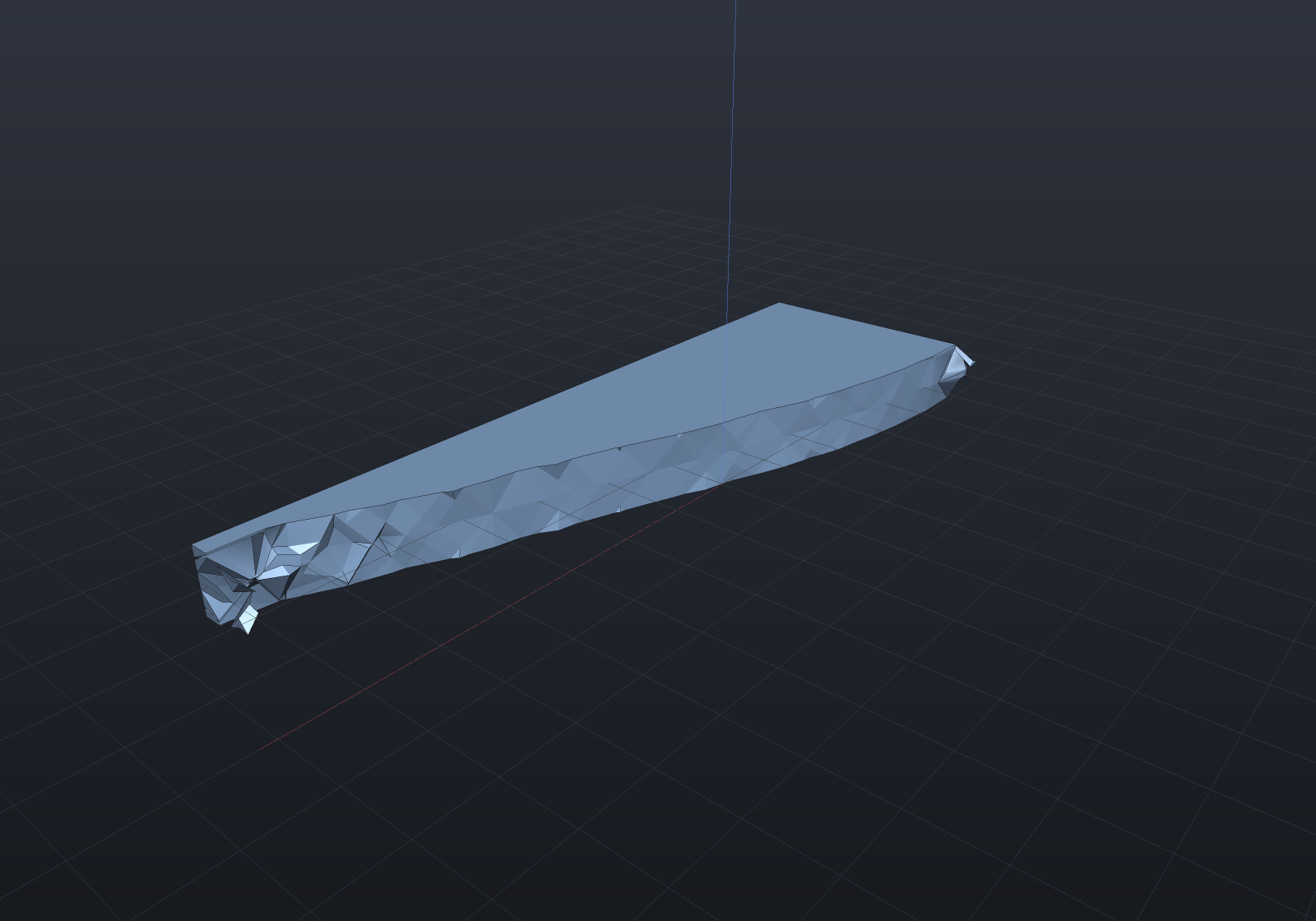
At a threshold of 0.5 this comes out as 0.3452 of the design space against the 0.35 that
was asked for — the gap is small here precisely because the field is nearly discrete, and on a
grey design it would not be. That is the number to read before believing a threshold, and it is
why ExtractedVolumeFraction exists as a measurement rather than the 0.5 being assumed to be
volume-preserving.
ExtractSurface marches the mesh’s own tetrahedra, which is exact for the piecewise-linear
nodal field and introduces no second discretisation. It is deliberately not Sdf + Surface Nets,
this repository’s usual answer to “polygonise a field”, for a reason with teeth:
SurfaceNets.Polygonize culls blocks using the 1-Lipschitz property of a signed distance
field, and a density field is not 1-Lipschitz and has no useful bound — it goes from 0 to 1
across one element, whatever an element’s size happens to be. The cull would drop surface
silently.
A B-Rep is refused by name. The level set of a piecewise-linear field is a faceted surface
with as many facets as the mesh has crossings, and there is no parametric surface in it to
recover — offering one would mean fitting, whose tolerance would silently become part of the
answer. Re-modelling the result by hand is a step every topology-optimisation workflow has, and
Shape.From(...) is where it starts.
What it refuses, and why each is wrong rather than hard
| refused | why the sensitivity would be wrong |
|---|---|
Gravity / BodyForce | self-weight is design-dependent: it is integrated over the full-density body once, so a run would minimise one structure’s compliance under a different structure’s weight — and with a load that moves with the design, compliance stops being self-adjoint |
| a prescribed non-zero displacement | the applied force then moves with the stiffness, so minimising f'u makes the structure as compliant as possible. The sign of the whole problem flips |
| a thermal load | alpha·dT enters through D, so the load scales with rho^p — design-dependent by construction |
| local stress constraints | they need aggregation (p-norm or Kreisselmeier–Steinhauser), and the aggregation parameter changes the answer, so it is a separate feature with its own verification rather than a flag on this one |
Nothing here publishes a stress, and that is deliberate: the stiffness carries a penalised modulus, so an element’s stress would be the SIMP stress rather than a physical one.
Passive regions and several load cases
Pin material that must stay or must go. SolidRegion and VoidRegion are
Func<Vector3d, bool> predicates over element centroids — a volume selector, matching
TetMeshOptions.SizingField, because Facets selects boundary facets and this wants the
interior:
var result = TopologyOptimizer.Minimize(model, new TopologyOptions{ VolumeFraction = 0.4, FilterRadius = 3.0, SolidRegion = c => (c - bearingBore).Length < 8, // keep material around the bore VoidRegion = c => c.Y > 40, // a clearance keep-out});A pinned element keeps density 1 or the floor and drops out of the redistribution, so the constraint still holds exactly with the passive material counted toward it. It is a bound, not a new algorithm — and it can only ever raise compliance, because a passive-constrained design is also a valid free design at the same volume.
Optimise against several loads at once. Minimize(cases, options) minimises the weighted-sum
compliance Σ w_i·u_i'Ku_i over a list of (model, weight) cases that share one mesh, supports
and materials (only the loads differ), so one factorization serves them all:
var result = TopologyOptimizer.Minimize( [new TopologyLoadCase(pushDown, 1.0), new TopologyLoadCase(pushSideways, 1.0)], options);The weighting is yours because it is the design decision — a min-max worst-case formulation is a different problem, filed.
Keep only the largest piece. TopologyReleaseOptions.KeepLargestComponentOnly drops
disconnected islands from the released surface — off by default, because silently deleting
material the optimiser placed should be a stated act, and even on it leaves ComponentCount
reporting what the extraction found.
What is verified
Not “it looks like a truss” — that is this feature’s actual failure mode, since a plausible picture is persuasive and no other output in this repository flatters itself so readily. The published 99-line-paper compliances are also not reproducible here and pretending otherwise would be worse than useless: those are 2D plane-stress figures on structured quadrilaterals, while this solves 3D elasticity on tetrahedra. What is asserted instead:
| claim | measured |
|---|---|
uniform bar, c = c0/f^p (closed form) | exact to 9 decimals at p = 1 and p = 3 |
stepped bar reaches the fully-stressed design rho_i ∝ N_i (closed form) | compliance within 0.04% and 0.12% of (L/2)(N1+N2)²/(2fEA); half-means 0.5997 / 0.2004 against 0.6 / 0.2 |
| the sensitivity against a central finite difference | worst relative difference 1.8e-7 unfiltered, 9.9e-8 through the density filter’s chain rule |
c = f'u against sum rho^p·(u_e' k0 u_e) | 1.5e-15 relative — two constructions, one answer |
| the volume constraint at every iteration | worst relative miss 7e-16 |
| compliance monotone under the update | 0 rises over 60 iterations, all three filters |
refining at fixed r_min keeps the structure | 0.014 / 0.014 filtered against 0.137 / 0.068 unfiltered (cantilever); 0.03 / 0.03 (MBB) |
| extraction of a uniform field | exactly the body’s own volume |
| extraction of a linear field | exactly the analytic slab, to 8 decimals |
| the MBB optimum is left–right symmetric | mean |density − mirror| at round-off; an off-centre load breaks it by 3× |
| pinned-solid / pinned-void elements hold density 1 / the floor | exact to 12 decimals; whole-domain fraction still met to round-off |
| a passive constraint raises compliance | forcing a hole through a cantilever’s tension corner +54.8%, material into the idle tip +6.2% |
| two mirror loads give a mirror-symmetric structure | two-case mirror difference 18% of a single case’s (residual is the Kuhn mesh’s own asymmetry) |
KeepLargestComponentOnly drops an island by its own volume | exact on a two-blob field; no-op on a connected one |
| smoothing moves the surface within a band | volume −6%, farthest vertex 0.73 mm — measured, and asserted inside a band |
| remeshing improves triangle shape | slivers 2 950 → 73, mean smallest-angle 21° → 48°, surface unmoved to 2e-14 |
| the released solid round-trips through STL | signed-tetrahedral volume matches the delivered volume to float precision; Validate-clean and closed |
Practical notes
- Linear elements are the right choice here, unlike buckling. Topology optimisation wants many small elements rather than few accurate ones, and every iteration pays for a factorization.
- AMD ordering is the default on this path, where it is opt-in elsewhere. The argument that makes it opt-in — a permutation is not bit-identical arithmetic and committed numbers were measured natural — does not apply to numbers a run produces for the first time, and a topology run pays for one factorization per iteration.
- Cost is one factorization per iteration. Measured on win-x64: 288 elements converge in
0.43 s, 1 152 in 2.5 s, 10 800 in about 50 s at 60 iterations. The reduced stiffness has an
identical sparsity pattern every iteration — mesh connectivity and eliminated DOFs are
fixed, only the per-element scales change — so the loop analyses the ordering and elimination
tree once (
SparseCholesky.AnalyzePattern) and each iteration runs only the numeric pass. It is a pure speedup (symbolic.Factorizeis bit-identical to a fresh factorization), but a bounded one: it removes the symbolic pass, which is a meaningful slice of a small factorization (1.13× at 1 152 elements) and almost nothing of a large one (1.02× at 10 800), because the numeric pass is the floor. PenaltyContinuationramps the penalty from 1 up toPenalty— holding at each level so the convexp = 1problem settles first — rather than penalising from the start. The convex problem has a unique optimum, so starting there and stepping up reduces how much the answer depends on the starting design: on a multimodal MBB fixture, two very different starts land 0.202 apart under fixedp = 3(one of them trapped at nearly twice the compliance) and 0.001 apart with continuation. It is off by default because it changes the answer — a deliberate choice, not a silent improvement.TopologyResult.MeanNeighbourssays how much neighbourhood the radius found in this mesh. A value near 1 means the radius is smaller than an element, and a radius that small is refused by name.result.ToText()prints the per-iteration table a convergence plot is read off.
Thermal topology optimisation
The optimiser’s loop is nearly physics-blind, and MinimizeThermal is the measurement of
that claim: the density scales the conductance instead of the stiffness
(FeaAssembly.Conductance learned the optional per-element scale Stiffness already
carried — null skips the multiply, so every incumbent thermal assembly is bit-identical),
the field solved is temperature, and the OC iteration, filters, passive regions and volume
constraint carry over verbatim. The classic problem it solves is volume-to-point: a
generating region drained to a cold sink through a budget of high-conductivity material,
which optimises into the well-known dendrite.
var space = Shape.Box(40, 40, 5);var tets = TetMesher.Mesh(space.ToMesh(), new TetMeshOptions{ RefineQuality = true, MaxElementSize = 4, // coarse on purpose - this fence prints numbers, not a study});var material = new Material("conductor", 1, 0, 7.85e-9).WithThermal(200, 500e6);var model = new ThermalModel(AnalysisMesh.Of(tets), material);model.Temperature(Facets.OnPlane(new Vector3d(-20, 0, 0), Vector3d.UnitX), 0); // the ZERO sinkmodel.Generation(0.5); // the domain's own heatvar result = TopologyOptimizer.MinimizeThermal(model, new TopologyOptions{ VolumeFraction = 0.3, FilterRadius = 8.0, // a minimum member size: several elements wide MaxIterations = 80,});Console.WriteLine($"uniform smear {result.History[0].Compliance:0} -> dendrite " + $"{result.Compliance:0} ({result.Compliance / result.History[0].Compliance:P0} " + $"of the uniform design's thermal compliance, {result.Iterations} iterations)");The honest scope is conduction-dominated design, and each exclusion carries its reason:
convection is refused by name (a film on an evolving boundary is a load that moves with the
design, so compliance stops being self-adjoint — the same reason the structural optimiser
refuses self-weight); a nonzero prescribed temperature is refused too (the coupling term
K_fc·T_c scales with the density of the elements touching the sink), while a zero
prescribed temperature contributes nothing and is the volume-to-point sink — measure the
field as the rise above it. Generation stays fixed: the heat is the domain’s, not the
material’s (the electronics filling the void make it; the conductor drains it). Verified in
the structural optimiser’s own style: the p = 1 and p = 3 uniform closed forms are met
exactly (ratio 1.0 to ten digits), the sensitivity matches a central difference through
the production evaluator at 9.2e-8, f'T equals Σ ρᵖ·E_e to twelve digits, and the
dendrite reaches 25% of the uniform design’s compliance on the structured test
fixture (the coarser fence above measures its own 37% — the ratio is mesh-dependent, the
direction is not).