DXF & SVG (2D interchange)
Two-dimensional geometry leaves and enters EngrCAD through two writers and one reader, all dependency-free:
- DXF (
DxfDocument) — the interchange seam with drafting packages and laser/plasma/router CAM: LINE, ARC, CIRCLE, LWPOLYLINE, SPLINE and TEXT entities with layers, both directions. - SVG (
SvgDrawing) — drawings for documentation and browsers, with line-type control driven by edge classification (visible / hidden / section — the thing that makes an exported drawing usable rather than a flat soup of curves).
DXF out, DXF in
A sketch’s lines and arcs are written exactly: an LWPOLYLINE vertex carries a “bulge” (tan of a quarter of the arc’s sweep), which encodes a circular arc with no flattening, and a full-circle loop becomes a CIRCLE entity. Cubic béziers flatten at a stated chord tolerance by default, or become exact SPLINE entities — see below. This snippet round-trips on every docs build and checks the exact area survived:
var plate = Sketch.RoundedRectangle(40, 24, 6);
var dxf = new DxfDocument();dxf.Add(plate, layer: "outline");dxf.Add(Sketch.Circle((-12, 0), 3), layer: "holes");dxf.Add(Sketch.Circle((12, 0), 3), layer: "holes");dxf.SaveFile(Path.Combine(Scratch, "plate.dxf"));
var loaded = DxfDocument.LoadFile(Path.Combine(Scratch, "plate.dxf"));var sketches = loaded.ToSketches(out var diagnostics);if (diagnostics.Count != 0) throw new Exception(string.Join("; ", diagnostics));if (sketches.Count != 3) throw new Exception($"expected 3 loops, got {sketches.Count}");
// The arc encoding is exact, so the area survives to full precision.double error = Math.Abs(sketches[0].Area() - plate.Area());if (error > 1e-9) throw new Exception($"area drifted by {error:e2}");
Reading is diagnostic, never throwing: unknown entities are skipped and counted,
loose LINE/ARC entities are chained end-to-end into closed loops at the weld
tolerance, and anything that does not close is reported, not invented. An imported
sketch is a first-class Sketch — extrude it, revolve it, use it as a hole.
var dxf = new DxfDocument();dxf.Add(Sketch.Slot(30, 10), layer: "profile");dxf.SaveFile(Path.Combine(Scratch, "slot.dxf"));
var profile = DxfDocument.LoadFile(Path.Combine(Scratch, "slot.dxf")).ToSketches().Single();var solid = Shape.Extrude(profile, 8);if (!solid.ToMesh().IsClosed) throw new Exception("imported profile should extrude clean");
Cubics, exactly: SPLINE entities
A cubic Bézier is a clamped degree-3 B-spline with four control points, so DXF’s
SPLINE entity carries one with nothing approximated. DxfCurveMode.Spline uses it:
var wave = Sketch.Start(0, 0)    .BezierTo((3, 4), (7, -4), (10, 0))    .LineTo(10, -3).LineTo(0, -3).Close();
var dxf = new DxfDocument();dxf.Add(wave, layer: "profile", curves: DxfCurveMode.Spline);dxf.SaveFile(Path.Combine(Scratch, "wave.dxf"));
var back = DxfDocument.LoadFile(Path.Combine(Scratch, "wave.dxf")).ToSketches().Single();
// Exact, not "within a chord tolerance": the area survives to full precision.double error = Math.Abs(back.Area() - wave.Area());if (error > 1e-9) throw new Exception($"area drifted by {error:e2}");
The cost is structural rather than numerical, and it is worth knowing before you choose:
a loop containing a cubic arrives as a chain of entities (LWPOLYLINE runs of lines
and arcs, one SPLINE per cubic) instead of one closed polyline, because DXF’s polyline
vocabulary has no cubic vertex. ToSketches chains it back by endpoint, so the round
trip is exact either way — but a CAM post that expects one closed polyline per part will
prefer the default. A sketch with no cubics writes byte-for-byte the same file under
either mode, so the choice only ever affects Béziers.
Any polynomial spline, whatever its knots
Reading is no longer narrower than writing. A degree-1 spline is its own polyline; anything else goes through Bézier decomposition — knot insertion to full interior multiplicity (The NURBS Book A5.6), with an unclamped or uniform knot vector clamped first — which is a change of basis, so nothing is fitted or sampled. A file whose splines this library wrote is unaffected to the last bit: the insertion loop never runs where an interior knot’s multiplicity already equals the degree, so a Bézier-form spline decomposes to itself.
The shape worth showing is the one that used to be refused, because it is the one a careless reader gets plausibly wrong. Seven control points is a Bézier-compatible count (3k + 1), so splitting them four at a time produces a curve through the same endpoints and the wrong shape in between:
// A clamped cubic with SINGLE interior knots - a genuine B-spline of four spans, not a// chain of Beziers. Splitting its control points four at a time would be silently wrong.Vector2d[] control =[    (0, 0), (10, 18), (26, -14), (40, 6), (54, 20), (68, -10), (80, 0),];var document = new DxfDocument();document.Add(new DxfSpline(control, 3, [0, 0, 0, 0, 1, 2, 3, 4, 4, 4, 4]));document.Add(new DxfLine((80, 0), (80, -26)));document.Add(new DxfLine((80, -26), (0, -26)));document.Add(new DxfLine((0, -26), (0, 0)));
// Four knot spans, so four exact cubics - and nothing reported.var sketch = document.ToSketches(out var diagnostics).Single();if (diagnostics.Count != 0) throw new Exception(string.Join("; ", diagnostics));
var curves = sketch.ToCurves();int cubics = curves.Count(c => c is BezierCurve2d);if (cubics != 4) throw new Exception($"expected one exact cubic per knot span, got {cubics}");if (curves.Count != 7) throw new Exception($"expected 4 cubics + 3 lines, got {curves.Count}");
var scene = new Scene();scene.Add(new Part("profile", Shape.Extrude(sketch, 8)));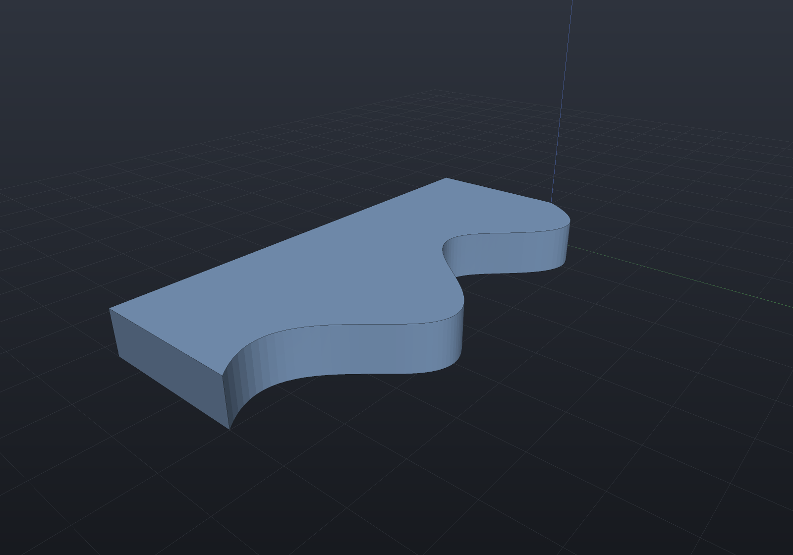
What is still refused is refused for the sketch’s reason rather than the decomposition’s, and the messages say which — the distinction matters, because the old message (“needs knot insertion”) read as a kernel gap:
- a rational spline decomposes perfectly well, into rational Béziers, and a sketch’s Bézier segment is polynomial with no exact rational form;
- a degree 4 or higher spline decomposes perfectly well too, and a sketch’s highest polynomial segment is a cubic, with no exact degree reduction.
var rational = new DxfDocument();rational.Add(new DxfSpline([(0, 0), (3, 4), (7, -4), (10, 0)], 3, [0, 0, 0, 0, 1, 1, 1, 1], [1, 2, 2, 1]));rational.ToSketches(out var why);if (!why.Single().Contains("POLYNOMIAL")) throw new Exception(why.Single());BSplineDecomposition.ToBezierSegments is public kernel API in EngrCAD.BRep, beside
BSplineBasis: it takes any degree and carries weights (insertion runs on homogeneous
coordinates), so a consumer that can hold a quartic or a rational piece gets one.
Units are declared, and honoured
Every file this writer produces states $INSUNITS in its header — millimetres by
default, DxfDocument.Units to change it. That is the same duty the LTYPE table has:
a file that does not say what its numbers mean leaves every reader to guess, and a
laser cutter that guesses inches for millimetres ruins a sheet.
On load the declaration is honoured rather than merely reported: an inch file’s
coordinates are scaled into millimetres (ModelUnits’ convention), the document comes
back labelled millimetres so re-saving it is correct, and a diagnostic names the original
unit and the factor. Unitless — the value a great many real files carry — is the file’s
honest “no claim” and is never scaled; inventing a factor for it would be exactly the
silent mis-scaling this exists to prevent.
var inches = new DxfDocument { Units = DxfUnits.Inches };inches.Add(Sketch.Circle((2, 0), 1));                       // a 1 inch radius at x = 2 ininches.SaveFile(Path.Combine(Scratch, "imperial.dxf"));
var loaded = DxfDocument.LoadFile(Path.Combine(Scratch, "imperial.dxf"));var circle = (DxfCircle)loaded.Entities.Single();if (Math.Abs(circle.Radius - 25.4) > 1e-9) throw new Exception($"radius {circle.Radius}");if (loaded.Units != DxfUnits.Millimetres) throw new Exception("should re-save as mm");
SVG with drawing conventions
SvgDrawing takes the output of 2D views — Shape.Section (regions
of the cut) and Shape.Silhouette (the projected outline) — plus exact sketches
(arcs as SVG A commands, cubics as C, nothing flattened). Each add states its
line class; each (layer, class) pair becomes an SVG group with the ISO 128-style
preset — visible solid, hidden dashed, section dash-dot — that a downstream editor
or CAM can toggle wholesale:
var housing = Shape.Box(40, 30, 20) - Shape.Cylinder(8, 50);
var top = SketchPlane.At((0, 0, 0), Vector3d.UnitX, Vector3d.UnitY);var drawing = new SvgDrawing();drawing.Add(housing.Silhouette(top), SvgLineClass.Visible, layer: "outline");drawing.Add(housing.Section(top), SvgLineClass.Section, layer: "cut");drawing.SaveFile(Path.Combine(Scratch, "housing.svg"));
var text = File.ReadAllText(Path.Combine(Scratch, "housing.svg"));if (!text.Contains("stroke-dasharray")) throw new Exception("section lines should be dash-dot");if (!text.Contains("scale(1,-1)")) throw new Exception("model space is y-up; the flip must be there");
The drawing is emitted in model millimetres (1 SVG user unit = 1 mm, viewBox sized
from the content), with one root scale(1,-1) handling SVG’s y-down convention so
every coordinate in the file matches the model’s.