CNC milling (2.5D)
CAM stage 2 — pocketing, profiling and drilling, and like the slicer it is a thin layer over
machinery that already shipped: pocket clearing is the inward-offset ladder (Region2dOffset
rings one stepover apart, an island’s grown boundary ridden like any other loop), profiling is
one outline offset by the tool radius (round joins — the path a tool centre physically rolls
around an outside corner), depth arrives in StepDown slices with the last clamped to the exact
stated depth, and drilling ships as expanded peck moves — plain G0/G1, so the same twin
decoder reads a drill cycle with nothing new.
The verification oracle is the morphological opening. A radius-r tool can reach exactly
grow_r(shrink_r(region)) — internal corners come back rounded — so the union of the passes’
swept footprints (each centreline stroked at the tool diameter: the machined-stock simulation)
must equal the opening, and a rectangular pocket’s unreachable corner residue is closed form:
(4 − π)·r². The no-gouge claim is exact and point-by-point: every pass point at least the tool
radius from the region boundary.
// The outline comes from the solid itself: a plate sectioned at mid-height.var plate = Shape.Box(40, 20, 6);var region = plate.Section(SketchPlane.At(new Vector3d(0, 0, 0), Vector3d.UnitX, Vector3d.UnitY))    .Single();
var tool = new MillTool(Diameter: 6, FeedRate: 600, StepDown: 2);var pocket = CncMill.Pocket(region, tool, depth: 4);var profile = CncMill.Profile(region, tool, depth: 6, ProfileSide.Outside,    tabs: 3, tabHeight: 2, tabWidth: 8);var drills = CncMill.Drill([new Vector2d(-15, 0), new Vector2d(15, 0)],    new MillTool(3), depth: 8, peck: 3);
Console.WriteLine($"pocket: {pocket.Passes.Count} passes, cut {pocket.CutLength:0} mm");Console.WriteLine($"profile: {profile.Passes.Count} passes (3 holding tabs on the last)");
// The corner residue a round tool cannot reach is closed form: (4 - pi) * r^2.double r = tool.Radius;var opening = Region2dBoolean.UnionAll(    [.. Region2dOffset.Offset(region, -r).SelectMany(s => Region2dOffset.Offset(s, r))]);Console.WriteLine($"unreachable corner residue: {region.Area - opening.Sum(o => o.Area):0.0000} "    + $"mm2 vs (4-pi)r2 = {(4 - Math.PI) * r * r:0.0000}");
// One G-code program; the twin decoder recovers the cut length (rapids separated by the// decoder's own Rapid flag, since feed state persists across G0 and G1 alike).var decoded = GcodeReader.Read(CncGcodeWriter.Write([pocket, profile, drills]));double cut = decoded.Moves.Where(m => !m.Rapid && m.XyLength > 0 && m.Feed == tool.FeedRate)    .Sum(m => m.XyLength);Console.WriteLine($"decoded cut length {cut:0} mm vs stated "    + $"{pocket.CutLength + profile.CutLength:0} mm");
// The pocket's ring ladder (one depth level), the outside profile pass and the drill// points, drawn over the translucent plate.var plate = Shape.Box(40, 20, 6);var region = plate.Section(SketchPlane.At(new Vector3d(0, 0, 0), Vector3d.UnitX, Vector3d.UnitY)) .Single();var tool = new MillTool(Diameter: 6, StepDown: 2);var pocket = CncMill.Pocket(region, tool, depth: 4);var profile = CncMill.Profile(region, tool, depth: 6, ProfileSide.Outside);
Shape Ribbons(IEnumerable<MillPass> passes){ var regions = new List<Region2d>(); foreach (var pass in passes) { var pts = pass.Points.Select(p => new Vector2d(p.X, p.Y)).ToList(); if (pass.IsClosed) pts.Add(pts[0]); regions.AddRange(Region2dOffset.Stroke(pts, 0.8)); } Shape? all = null; foreach (var r in Region2dBoolean.UnionAll(regions)) { var sketch = Sketch.Polygon(r.Outer); foreach (var hole in r.Holes) sketch = sketch.WithHole(Sketch.Polygon(hole)); var ribbon = Shape.Extrude(sketch, 0.5, SketchPlane.At( new Vector3d(0, 0, 3.2), Vector3d.UnitX, Vector3d.UnitY)); all = all is null ? ribbon : all | ribbon; } return all!;}
double topZ = pocket.Passes[0].Points[0].Z; // the first depth level's ringsvar scene = new Scene();scene.Add(new Part("plate", plate, Palette.Steel) { DisplayMode = DisplayMode.Translucent });scene.Add(new Part("pocket rings", Ribbons(pocket.Passes.Where(p => p.Points[0].Z == topZ)), Palette.Coral));scene.Add(new Part("profile", Ribbons(profile.Passes.Take(1)), Palette.Sky));scene.Add(new Part("drills", Shape.Cylinder(1.5, 0.5).Translate(-15, 0, 3.2) | Shape.Cylinder(1.5, 0.5).Translate(15, 0, 3.2), Palette.Brass));var camera = new CameraState(-Math.PI / 2 + 0.4, 0.9, 62, (0, 0, 0));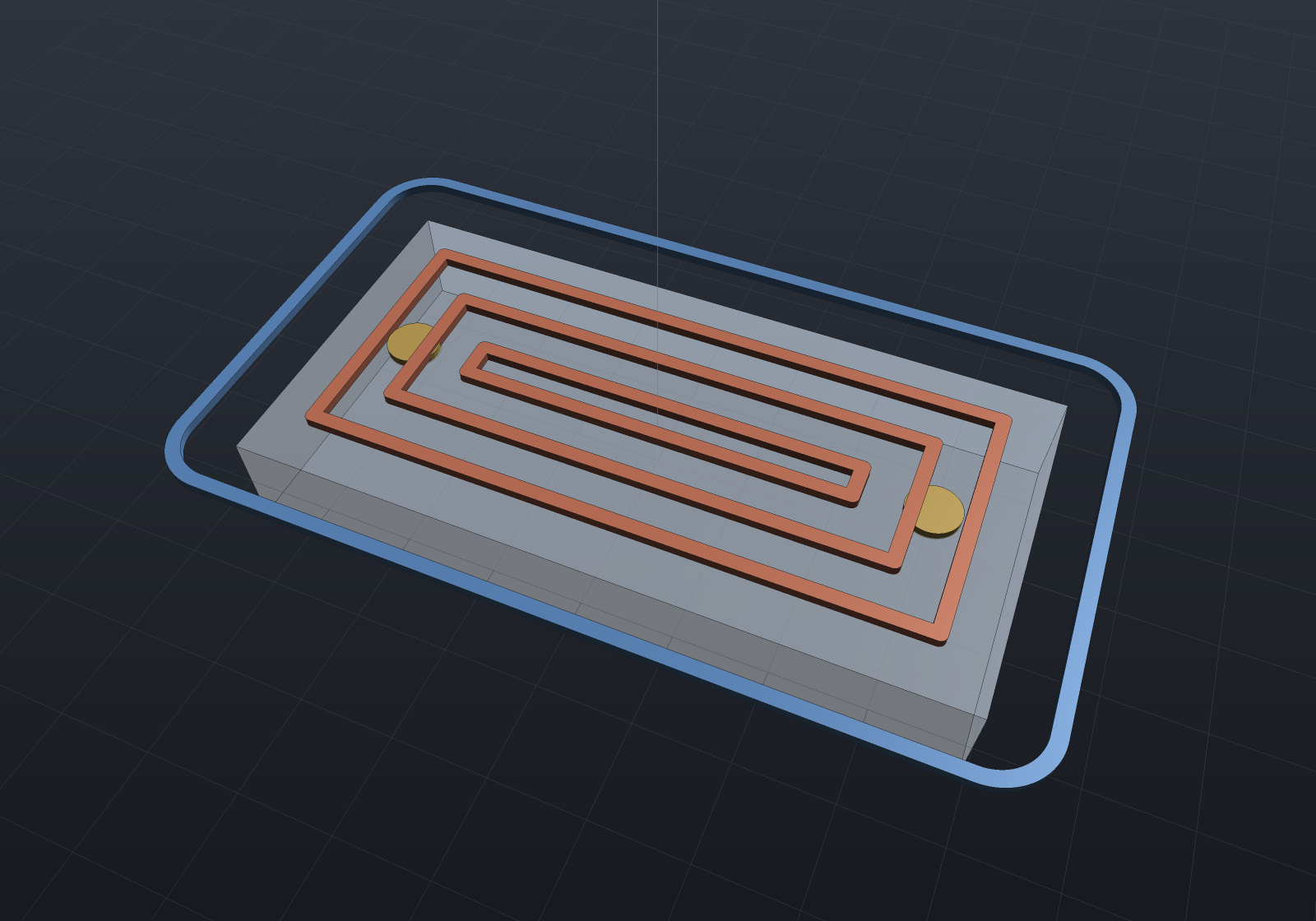
Moves mean what their shape says. Within a pass, an XY move cuts at the feed rate, a
straight-down move plunges at the plunge rate, a straight-up move retracts as a rapid — one
MillPass vocabulary carries pockets, tabbed profiles and pecked drills with no per-move
annotations. Holding tabs live on the final profile pass only, evenly spaced by arc length (a
stated convention, not rounding luck), each a vertical rise at the tab’s own edge — never a
diagonal ramp that would leave the closing stretch part-cut.
Lead-in/out arcs are opt-in on Profile (leadRadius:): each loop is entered and left
on a quarter arc tangent to the path at the seam, on the side away from the material —
which the climb/conventional winding contract has already made a travel-relative fact
(climb puts material left of travel, so away is right), so no per-loop kind flag exists to
get wrong. The point is the plunge: the writer always plunges at a pass’s first point,
and with the lead prepended that point is the arc’s start, off the wall — a plunge on the
profile dwells and marks it. A lead that cannot fit (a small hole’s far wall inside the
arc’s reach) refuses by name with the measured shortfall; zero is byte-identical.
MillTool carries the process numbers (feeds in mm/min — G-code’s F verbatim), and its
Stepover ≤ 0.5 is the value that provably covers the whole reachable area (each ring clears
± a radius about its centreline).
The machined-stock simulation
CncStock.Simulate records the stock at N fractions of the total cut length — each state an
ordinary Shape a scene can show, export or measure. The swept volume of a 2.5D pass is
closed form: a tool at constant z occupies its stroked footprint from the cut level up
through the stock, and a vertical descent bores a disc (an inscribed 32-gon, so a drilled
state’s volume is an exact prism — polyhedral mesh booleans are exact, which is what makes
the drill check an identity rather than a tolerance). The removal is subtracted as z bands
(one level to the next), so successive levels repeating one footprint never hand the boolean
two coincident side walls:
var stock = Shape.Box(30, 22, 8).Translate(0, 0, -4); // stock top at z = 0var region = new Region2d(    [new Vector2d(-9, -6), new Vector2d(9, -6), new Vector2d(9, 6), new Vector2d(-9, 6)]);var tool = new MillTool(Diameter: 4, StepDown: 2);var ops = new[]{    CncMill.Pocket(region, tool, depth: 3),    CncMill.Drill([new Vector2d(-12, 8), new Vector2d(12, 8)], new MillTool(3), depth: 6),};
foreach (var state in CncStock.Simulate(stock, ops, states: 5))    Console.WriteLine($"fraction {state.Fraction:0.00}: cut {state.CutLength,6:0.0} mm, "        + $"stock {state.Shape.ToMesh().Volume():0.0} mm3");
// The drilled bore is EXACT: an inscribed 32-gon prism, closed form to round-off.double r = 1.5;double bore = 32 / 2.0 * r * r * Math.Sin(2 * Math.PI / 32) * 6;Console.WriteLine($"each bore removes exactly {bore:0.000000} mm3");
// The stock mid-cut: the pocket part-cleared, one bore drilled, the second still to come.var stock = Shape.Box(30, 22, 8).Translate(0, 0, -4);var region = new Region2d( [new Vector2d(-9, -6), new Vector2d(9, -6), new Vector2d(9, 6), new Vector2d(-9, 6)]);var ops = new[]{ CncMill.Pocket(region, new MillTool(Diameter: 4, StepDown: 2), depth: 3), CncMill.Drill([new Vector2d(-12, 8), new Vector2d(12, 8)], new MillTool(3), depth: 6),};var states = CncStock.Simulate(stock, ops, states: 5);
var scene = new Scene();scene.Add(new Part("stock", states[3].Shape, Palette.Steel));var camera = new CameraState(-Math.PI / 2 + 0.5, 0.6, 55, (0, 0, -3));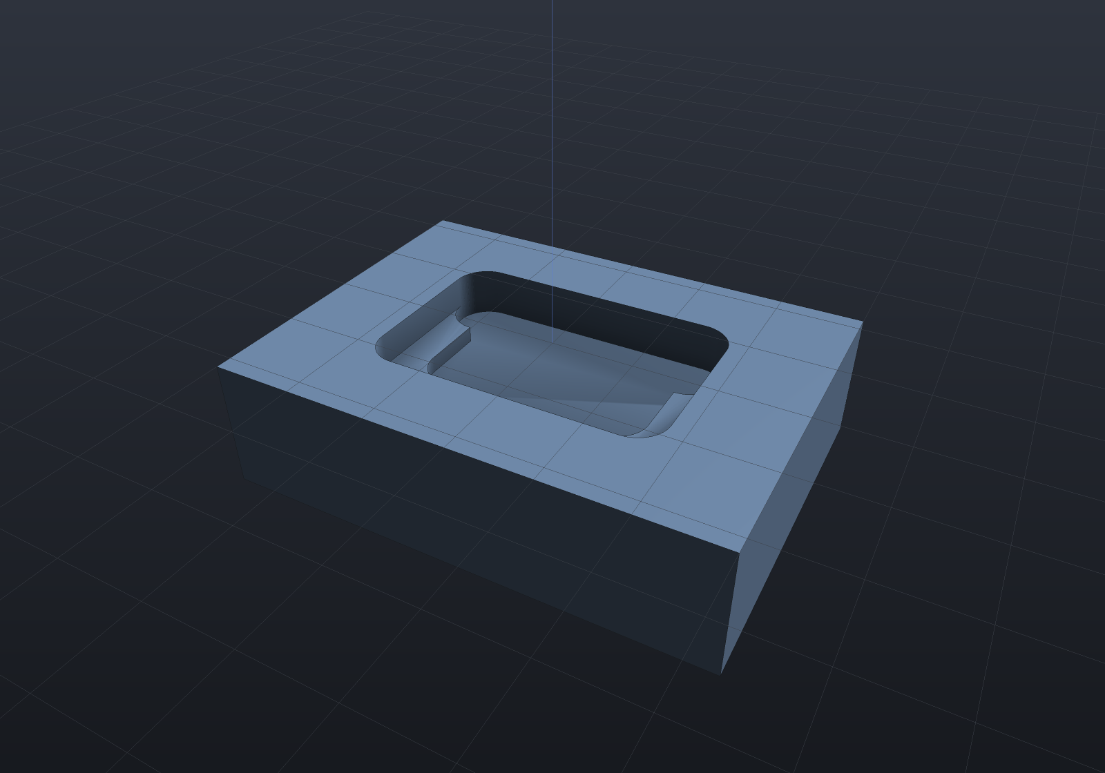
A state is a still or an export, deliberately not a live clip: a changing-geometry animation has no matrices-only form (the pose-track contract is that only matrices move), so the states are recorded data — the same reasoning that kept transient thermal playback off the deformation uniform. The TOOL, though, animates as an ordinary pose track: matrices only, riding the animation system with nothing new —
// The tool riding its own toolpath over the machined stock — matrices only.var stock = Shape.Box(30, 22, 8).Translate(0, 0, -4);var region = new Region2d(    [new Vector2d(-9, -6), new Vector2d(9, -6), new Vector2d(9, 6), new Vector2d(-9, 6)]);var pocket = CncMill.Pocket(region, new MillTool(Diameter: 4, StepDown: 2), depth: 3);var machined = CncStock.Simulate(stock, [pocket], states: 2)[^1].Shape;
var scene = new Scene();scene.Add(new Part("stock", machined));scene.Add(new Part("tool", Shape.Cylinder(2, 14).Translate(0, 0, 7), Palette.Coral));
// The tool part is modeled with its TIP at the origin, so following the pass points// puts the tip on the cut; a closed ring appends its own first point to complete.var waypoints = pocket.Passes    .SelectMany(p => p.IsClosed ? p.Points.Append(p.Points[0]) : p.Points).ToList();var animation = new Animation(durationSeconds: 6)    .With(PathTracks.Follow(scene, "tool", waypoints));
PathTracks.Follow maps t to arc length (the explode-path rule — constant speed through
every corner, however unevenly the waypoints are spaced), hits each waypoint exactly at its own
parameter, and leaves every other instance’s matrix untouched bit-for-bit.
HSM: trochoidal slotting
Stage 4’s defining invariant is the engagement angle — the arc of tool circumference in
material. A conventional slot cut buries the tool’s whole leading half (~180°), which is why
slotting is where cutters die; CncHsm.TrochoidalSlot keeps it bounded: an Archimedean
spiral-out entry, then circular loops advancing a small step per revolution, so each loop
shaves a thin crescent off material the previous loops already opened.
The advance is solved against the measured quantity, because the textbook formula is
measurably wrong here. A straight cut of radial width a engages acos((r − a)/r) — but a
trochoid cuts against the previous loop’s convex swept boundary, which engages more of the
circumference at the same radial width: seeding the advance from the straight-cut relation at
a 60° bound measured 90° from the evolving stock. So the constructor bisects the advance
against a steady-state model of the same rule the tests measure with (several loops, the last
loop’s tool-circle arc not yet covered by the swept prefix), and the verification re-measures
the real path independently — two constructions checking each other:
var tool = new MillTool(Diameter: 4);var slot = CncHsm.TrochoidalSlot(new Vector2d(0, 0), new Vector2d(20, 0), slotWidth: 10, tool, depth: 4, maxEngagementDegrees: 60);Console.WriteLine($"{slot.Passes.Count} depth levels, " + $"{slot.Passes[0].Points.Count} points per level, cut {slot.CutLength:0} mm");Console.WriteLine($"a straight slot is 20 mm of cut — the trochoid spends " + $"{slot.Passes[0].CutLength / 20:0.0}x of path for a bounded tool load");// The trochoid itself: an Archimedean spiral-out, then loops advancing the solved step// per revolution, one finishing loop at the far end. The figure opens the engagement// bound so the loops read — at a production 60° they pack too tightly to tell apart.var tool = new MillTool(Diameter: 4);var slot = CncHsm.TrochoidalSlot(new Vector2d(-5, 0), new Vector2d(5, 0), slotWidth: 9, tool, depth: 2, maxEngagementDegrees: 110, samplesPerLoop: 36);var path = slot.Passes[0].Points.Select(p => new Vector2d(p.X, p.Y)).ToList();
Shape? ribbon = null;foreach (var r in Region2dBoolean.UnionAll([.. Region2dOffset.Stroke(path, 0.18)])){ var sketch = Sketch.Polygon(r.Outer); foreach (var hole in r.Holes) sketch = sketch.WithHole(Sketch.Polygon(hole)); var piece = Shape.Extrude(sketch, 0.4, SketchPlane.At( new Vector3d(0, 0, 0.3), Vector3d.UnitX, Vector3d.UnitY)); ribbon = ribbon is null ? piece : ribbon | piece;}
var scene = new Scene();scene.Add(new Part("stock", Shape.Box(20, 14, 4).Translate(0, 0, -2), Palette.Steel) { DisplayMode = DisplayMode.Translucent });scene.Add(new Part("trochoid", ribbon!, Palette.Coral));var camera = new CameraState(-Math.PI / 2, 1.1, 26, (0, 0, 0));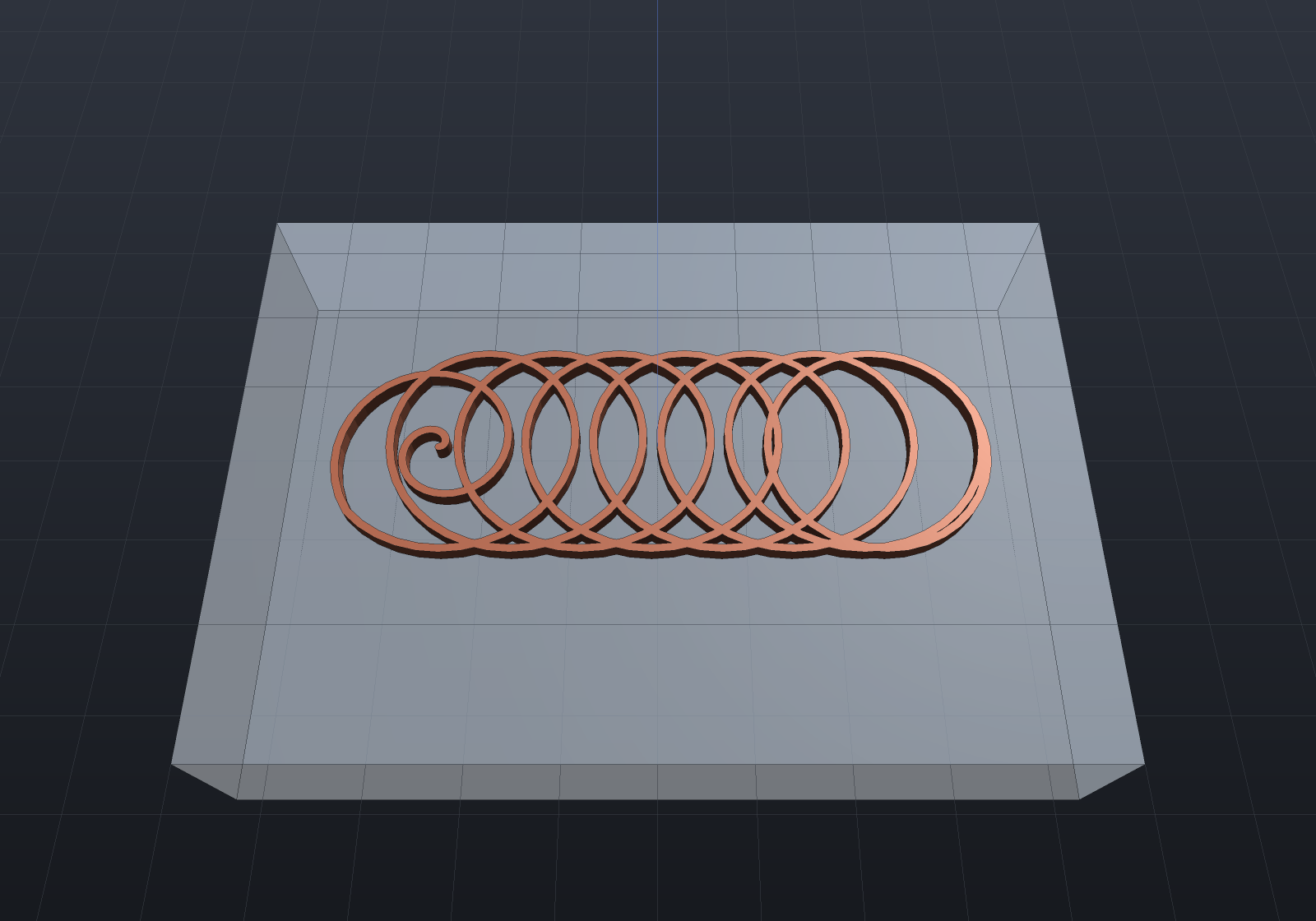
The entry spiral’s honesty is stated rather than hidden: a spiral-out’s contact arc is
wide but shallow — its bounded quantity is the radial step per turn (the chip load), which
is why entry feed reduction exists — so the arc bound is a claim about the trochoidal phase,
measured from one full loop after the spiral reaches the loop radius. The slot’s swept
footprint is the stadium L·W + π(W/2)² (asserted within 2%), and no path point ever leaves
the slot corridor (no-overcut, point by point).
Drilling from the model
CncDrilling.FromShape/FromPart derives the drill program from the model’s own hole
declarations — the one-declaration rule at the CAM boundary: a Shape.Drill or
Shape.ThreadedHole call already states the diameter, the depth and the positions (it is
what the drawing’s HoleTable letters), so the CNC program reads the same rows rather
than having coordinates transcribed beside the model. One operation per distinct drill
diameter, ascending — a real setup is one tool per diameter — with a counterbore
contributing its through bore (the larger feature is a milling operation, not a drill)
and a threaded hole its tap-drill pilot. Depth is to the shoulder, which is the
drill-cycle convention too, so a real drill’s tip reaches deeper exactly as the model’s own
WithTipAngle draws it; a hole on a tilted plane refuses naming its row letter (which face
goes up is the fixture’s decision, never a silent re-pose).
var plate = Shape.Box(60, 40, 8) .Drill(StandardHoles.Clearance(5), [(-20, 10), (-20, -10), (20, 10), (20, -10)], depth: 10) .ThreadedHole(StandardThreads.Metric(6), [(0, 10), (0, -10)], depth: 6);var ops = CncDrilling.FromShape(plate);foreach (var op in ops) Console.WriteLine($"{op.Name}: {op.Passes.Count} holes");var gcode = CncGcodeWriter.Write(ops, cannedDrilling: true);Console.WriteLine($"{gcode.Split('\n').Count(l => l.StartsWith("G83"))} G83 cycles " + "- the M6 rows drill their tap pilot, the clearance rows their bore");Helical ramp entry
Pocket(..., rampAngleDegrees: 3) replaces every straight plunge into material with a
helix descending from the previous — already cleared — level about the level’s own first
point: radius under the tool radius (no core post is left), inside the measured room, pitch
2π·r·tan(angle), one flat closing turn at the level so the ramp’s floor is cleared. The
level’s rings then run as one pass linked at depth (a link cut through one stepover of
web) wherever the straight link stays a tool radius clear of the boundary — exact
segment-to-segment distance, so a link across a concave pocket’s gap is refused rather than
gouged — and a pocket too tight to helix falls back to the plunge, honestly. The oracle is
that every stationary-XY descending move ends at a level top (cleared air), where the
plunge-only program’s end at the level bottoms, in material; ramp 0 is byte-identical.
Landing it fixed a pre-existing ordering defect: the ring ladder linked all of a level’s loops in ONE nearest-endpoint pass, which is pen-dependent and measurably started a level at its boundary ring — contradicting the module’s own innermost-first contract and the climb rule’s “inward is already cleared” premise. Loops now link within each ring level, innermost first, in both the plunged and the ramped emission.
Rest machining
CncMill.PocketRest(region, roughTool, finishTool, depth) clears what the rough pocket
could not reach — the corner residues of the morphological opening — with the smaller tool.
The rest region is region − opening(region, R₁), and each residue piece is pocketed over
intersect(grow(piece, 2·r₂), region): the grow is a derived sufficiency, not a margin
(for any reachable residue point there is a tool disc within 2·r₂ of it and inside the
region, so its centre lands in exactly the inset the ring ladder walks), letting the tool
centre stand in already-cleared space — the whole point of rest machining, since the residue
is usually smaller than the tool — while the intersect keeps the wall inviolate, so the
no-gouge claim against the original boundary survives point by point. Residues thinner
everywhere than a stated minimum (default r₂/4) are flattening noise, skipped rather than
chased with micro-passes.
var region = new Region2d(new List<Vector2d> { new(0, 0), new(40, 0), new(40, 24), new(0, 24) });var rough = new MillTool(12, StepDown: 3);var finish = new MillTool(3, StepDown: 3);var restOp = CncMill.PocketRest(region, rough, finish, depth: 3);// The residue ladder in closed form: (4−π)R² per tool — roughing leaves 30.9 mm²,// the rest pass takes it to the finish tool's own 1.93 mm², a 16× improvement.Console.WriteLine($"rough residue {(4 - Math.PI) * 36:0.0} mm² -> " + $"finish residue {(4 - Math.PI) * 2.25:0.00} mm²");Console.WriteLine($"rest pass: {restOp.Passes.Count} passes, " + $"cut length {restOp.CutLength:0.0} mm");The oracle is the module’s own opening identity, extended: the combined rough+rest
footprint equals the finish tool’s opening of the region (asserted within 1%), and what
remains uncovered is exactly (4−π)r₂² — the closed-form ladder. One arrangement lesson
paid for: the opening touches the wall tangentially at every residue cusp, the 2D
arrangement’s hostile case, so it is grown by an ε before the difference — transversal
contact, at the cost of an ε-band of residue the 2·r₂ grow immediately wins back.
Climb, conventional and canned cycles
Every pocket and profile takes a MillDirection (climb is the default), and the rule is
derived rather than transcribed: an M3 right-hand cutter viewed from +Z spins clockwise,
so a tooth at the contact point with material on the LEFT of travel moves with the feed —
the chip starts thick, which is climb milling. Hence climb walks a loop counter-clockwise
when the material is inside it (an outside profile around the part) and clockwise when the
material is beyond it (a pocket ring, an inside profile) — with an island pocket orienting
its outer-derived and island-derived rings oppositely, both read off the measured shoelace
sign, never assumed from the offset machinery’s emission order. The direction changes
traversal only: same passes, same starts, same cut length.
CncGcodeWriter.Write(ops, cannedDrilling: true) re-spells drill passes as canned cycles —
G81 for a single plunge, G83 Q for pecks, under G98, closed by G80 — with Z/R/Q
reconstructed from the pass’s own moves and verified against the peck arithmetic (an
irregular ladder falls back to expanded emission, which is always correct). The decoder
expands cycles under the Fanuc semantics, modal bare-X/Y re-execution included, and refuses
a cycle missing its Z, R or Q by name — a guessed drill depth is confidently wrong geometry.
The canned spelling pecks from the R plane, so its bites sit R above the expanded twin’s:
conservative, never a deeper bite, with the sites and final depths identical through the
decoder.
Feeds and speeds
CncToolLibrary.Suggest derives a starting MillTool from the ⚠ verify-against-datasheet
MillMaterials catalogue (nominal carbide figures, asserted in the chart’s own units) — the
two identities a feeds chart is built on: rpm = 1000·Vc/(π·D) and
feed = rpm × flutes × chip load, the chip load a stated fraction of the diameter. The
spindle cap preserves the chip load, not the feed — a capped rpm drops the feed in
proportion, because holding the feed would thicken every chip past what the flute clears:
foreach (var material in MillMaterials.All){ var tool = CncToolLibrary.Suggest(material, diameter: 6); Console.WriteLine($"{material.Name,-16} Ø6 2-flute: " + $"{tool.SpindleRpm,6:0} rpm, feed {tool.FeedRate,5:0} mm/min");}var small = CncToolLibrary.Suggest(MillMaterials.Aluminum6061, 2, maxRpm: 24000);Console.WriteLine($"Ø2 in aluminium wants ~40k rpm; capped at 24k the feed follows: " + $"{small.FeedRate:0} mm/min (chip load preserved)");Laser cutting
CncLaser.Cut is the 2D machinery’s near-free adjacent: a part cut free of sheet stock with
the kerf spent in the waste, and one outward offset gives every beam path with the
compensation already right — growing the region by kerf/2 moves its outer loops out into
the waste and its hole loops in into the holes, which are exactly the two beam
centrelines, so the freed part measures exactly the drawn dimensions with no per-loop case
analysis. Holes cut first (the release rule: a freed part is no longer held by the
sheet, so anything cut after the perimeter drifts). The G-code is GRBL’s laser flavour —
M4 dynamic power (the beam gates off during G0 travels by the controller’s own rule),
one S word, and no Z anywhere, because a laser has no depth axis and emitting one
would make the file mean something on the wrong machine.
var part = new Region2d( new List<Vector2d> { new(0, 0), new(40, 0), new(40, 20), new(0, 20) }, [new List<Vector2d> { new(15, 5), new(15, 15), new(25, 15), new(25, 5) }]);var cut = CncLaser.Cut(part, new LaserTool(KerfWidth: 0.2, Power: 750, Passes: 2));Console.WriteLine($"{cut.Passes.Count} paths, hole first; beam path {cut.CutLength:0.00} mm");Console.WriteLine($"outer = 2(40+20) + 2*pi*0.1 = {2 * (40 + 20) + 2 * Math.PI * 0.1:0.00} " + "(round corners carry the kerf compensation exactly)");var decoded = GcodeReader.Read(CncLaser.WriteGcode(cut));Console.WriteLine($"decoded cut length {decoded.Moves.Where(m => !m.Rapid).Sum(m => m.XyLength):0.0} mm " + "= 2 passes of every path");Arc output (G2/G3)
There are two routes to an arc in the file, and which one you get is decided by what the toolpath was built from rather than by a switch: a pass built on the exact curved tier carries its arcs and the writer transcribes them, while a pass that is only a polyline can have arcs recovered from it by the opt-in fitter.
Native arcs — the source said “arc”
CncMill.Profile and CncMill.Pocket have overloads taking a CurvedRegion2d, the exact
2D tier where a circular arc stays a circular arc through an offset. Those routes offset with
CurvedRegion2dOffset, so a tool-compensated corner is an arc, and the MillPass carries
it as a MillArc span — a stretch of the pass polyline that the writer emits as one
G2/G3. No fitter runs and no sagitta cap guards it: the fitter’s cap exists because
four points can be exactly concyclic by accident, and an arc that declares itself cannot be.
The polyline stays the universal representation. An arc-native pass’s Points are exactly
the flattened path at CncMill.ArcChordTolerance, so the stock simulation, the travel linker,
the coverage oracle and every other polyline consumer read what they always read; the arcs are
purely additive.
The assertion with teeth is the exact perimeter. A 40×24 plate with r6 corners profiled
outside by a Ø6 tool has a tool-centre outline of exactly 2(28 + 12) + 2π·9, and the decoded
arc-native program reaches it to nine decimal places — no chord deficit at all. The chorded
route cannot, at any flattening density, because an inscribed polygon is shorter than its arc;
that deficit is a floor, not a tolerance. Note which decoded quantity carries the claim:
GcodeReader expands an arc at 5°, coarser than the 1e-3 source chords, so summing move
chords reads a perfect arc as short. GcodeMove.PathLength is r·|sweep| for a sub-move
expanded from an arc, which measures the geometry the file states with no discretization in
between.
var exact = Sketch.RoundedRectangle(40, 24, 6).ToCurvedRegions()[0];var op = CncMill.Profile(exact, new MillTool(6), depth: 2, ProfileSide.Outside);string gcode = CncGcodeWriter.Write([op]);foreach (var line in gcode.Split('\n').Where(l => l.StartsWith("G2 ") || l.StartsWith("G3 ")))    Console.WriteLine(line);
var decoded = GcodeReader.Read(gcode).Moves.Where(m => !m.Rapid).ToList();double exactLength = decoded.Sum(m => m.PathLength);double chordLength = decoded.Sum(m => m.XyLength);double closedForm = 2 * (28 + 12.0) + 2 * Math.PI * 9;Console.WriteLine($"closed form           {closedForm:0.000000000}");Console.WriteLine($"decoded (PathLength)  {exactLength:0.000000000}");Console.WriteLine($"decoded (chords)      {chordLength:0.000000000}  <- the 5-degree expansion");
var flat = Sketch.RoundedRectangle(40, 24, 6).ToRegions()[0];var chorded = CncMill.Profile(flat, new MillTool(6), depth: 2, ProfileSide.Outside);double flatLength = GcodeReader.Read(CncGcodeWriter.Write([chorded]))    .Moves.Where(m => !m.Rapid).Sum(m => m.PathLength);Console.WriteLine($"chorded route         {flatLength:0.000000000}  <- short, at any density");
Fitted arcs — recovering them from a polyline
CncGcodeWriter.Write(operations, arcFitting: true) emits maximal runs of constant-z
points that lie on one circle as a single G2/G3 in the I/J centre-offset form instead
of the chord run — and this is recovery, not approximation: the offset machinery
places its corner vertices inscribed on the true tool-compensated arc, so the circle
fitted through them is the arc the chording lost. A 40×24 plate with r6 corners profiled
outside by a Ø6 tool emits exactly four arcs whose I/J radius is the compensated
6 + 3 = 9.
The guard that earns its keep is the sagitta cap: each accepted chord’s rise under the fitted arc must stay below the file’s own 1e-3 coordinate quantum. An on-circle test alone cannot protect the path, and the failing case is not hypothetical — IEEE negation is exact, so two points and their mirrors are exactly concyclic, and a symmetric part’s straight side flanked by its two corner tangency vertices reads as four points genuinely on a 675 mm circle whose arc would bulge 0.027 mm across the 12 mm side: a real gouge that every sample-based test waves through. Under the cap the substitution is invisible at the file’s own resolution, and the tests assert the no-gouge form directly (every decoded fitted point within 2e-3 of the source polyline).
GcodeReader decodes G2/G3 (I/J form) by expanding each arc into 5°-sampled
sub-moves, so every downstream identity — cut length, move kinds, extrusion conservation —
reads the arc as the fine polyline it machines as; the ambiguous R form, a missing
centre and endpoints that disagree about the radius refuse by name. Off is
byte-identical.
var region = Sketch.RoundedRectangle(40, 24, 6).ToRegions()[0];var op = CncMill.Profile(region, new MillTool(6), depth: 2, ProfileSide.Outside);string chords = CncGcodeWriter.Write([op]);string arcs = CncGcodeWriter.Write([op], arcFitting: true);Console.WriteLine($"chorded {chords.Split('\n').Length} lines -> fitted {arcs.Split('\n').Length}");foreach (var line in arcs.Split('\n').Where(l => l.StartsWith("G2 ") || l.StartsWith("G3 "))) Console.WriteLine(line);double length = GcodeReader.Read(arcs).Moves.Where(m => !m.Rapid).Sum(m => m.XyLength);Console.WriteLine($"decoded cut length {length:0.00} vs closed form " + $"2(28+12) + 2*pi*9 = {2 * (28 + 12.0) + 2 * Math.PI * 9:0.00}");A pass carrying arcs emits them whether or not the fitter is on, so the two compose: the
carried spans are transcribed and the fitter, if asked, works the stretches between them.
A pass carrying none behaves exactly as it always did — a polygonal construction emits no
G2/G3 at all with the fitter off.
Still filed with the campaign: arcs on a tabbed profile pass (a tab is resampled at
arc-length stations, so half an arc stated as a whole one would be a misresolve — the spans
are dropped rather than re-derived) and on a helical ramp entry (a helix’s chords carry a
Z word, which the planar arc carry deliberately does not spell), the 3-axis (surfacing) stock
simulation — a raster row’s swept volume is not a prism, so Simulate refuses it by name
today — and the trochoid ×
stock-record composition (the swept union’s scallop cusps are near-tangent crossings, the
mesh imprint boolean’s hostile family), plus general adaptive (constant-engagement) pocket
clearing, of which the closed-form cycloid family above is the honest first step.