CNC: 3-axis surfacing
Stage 3 of the CAM campaign — ball-nose finishing — is where the implicit engine pays
directly. The cutter-location surface of a ball-nose tool IS the field’s r-offset: a ball
of radius r touches the part exactly when its centre is at distance r from the surface. So
both strategies read the shape’s own SDF (Shape.ToImplicit()) instead of approximating an
offset mesh:
- Raster (parallel finishing) drops the tool at each sample by a sphere trace down the
vertical ray to the r-isolevel. The field’s 1-Lipschitz bound makes that gouge-free by
construction — a step of
sdf − rcan never cross the offset surface, so a stalled trace stops high (stock left, never a gouge). Rows are serpentine, grid-anchored (the slicer’s phase rule), and extend a tool radius past the part so the edge is machined. - Waterline (constant-z contouring) is the observation that the CL contour at a centre
plane is the SDF’s r-isolevel there —
SdfContours.OnPlane’s marching squares, chained into loops by its exact endpoint equality, then polished onto the isolevel by an in-plane Newton step (the correction must not leave the plane, or the pass stops being a waterline). On the steep walls waterline exists for, the path is exact to round-off.
// A dome on a plate, finished with a 4 mm ball-nose.var part = Shape.Box(24, 24, 6) | Shape.Sphere(6).Translate(0, 0, 3);var ball = new MillTool(Diameter: 4, StepDown: 2);
var raster = CncSurfacing.Raster(part, ball);var waterline = CncSurfacing.Waterline(part, ball);Console.WriteLine($"raster: {raster.Passes.Count} rows, cut length {raster.CutLength:0} mm; "    + $"waterline: {waterline.Passes.Count} contours on "    + $"{waterline.Passes.Select(p => p.Points[0].Z).Distinct().Count()} levels");
// The no-gouge claim is the field's own inequality: every ball CENTRE reads at least r.var sdf = part.ToImplicit();double worst = raster.Passes.SelectMany(p => p.Points)    .Min(p => sdf.Evaluate(new Vector3d(p.X, p.Y, p.Z + ball.Radius)));Console.WriteLine($"worst centre clearance {worst:0.#####} against r = {ball.Radius}");
// The scallop between rows is a chord identity — h = r − sqrt(r² − (s/2)²) — and the// stepover for a stated finish is its exact inverse.double s = ball.Stepover * ball.Diameter;Console.WriteLine($"scallop at a {s} mm stepover: {CncSurfacing.ScallopHeight(ball.Radius, s):0.###} mm; "    + $"a 0.01 mm finish needs {CncSurfacing.StepoverForScallop(ball.Radius, 0.01):0.###} mm");
// The same CncGcodeWriter carries surfacing passes — a move's meaning is its shape.string gcode = CncGcodeWriter.Write([raster, waterline], safeZ: 15);Console.WriteLine($"{gcode.Split('\n').Length} lines of G-code");
// The waterline contours in place: one CL loop per StepDown level, each an exact// r-isolevel of the part's own field, drawn at its tip height over the translucent part.var part = Shape.Box(24, 24, 6) | Shape.Sphere(6).Translate(0, 0, 3);var ball = new MillTool(Diameter: 4, StepDown: 2);var waterline = CncSurfacing.Waterline(part, ball);
Shape? rings = null;foreach (var pass in waterline.Passes.Where(p => p.IsClosed)){ var pts = pass.Points.Select(p => new Vector2d(p.X, p.Y)).ToList(); pts.Add(pts[0]); foreach (var r in Region2dBoolean.UnionAll([.. Region2dOffset.Stroke(pts, 0.4)])) { var sketch = Sketch.Polygon(r.Outer); foreach (var hole in r.Holes) sketch = sketch.WithHole(Sketch.Polygon(hole)); var ring = Shape.Extrude(sketch, 0.3, SketchPlane.At( new Vector3d(0, 0, pass.Points[0].Z), Vector3d.UnitX, Vector3d.UnitY)); rings = rings is null ? ring : rings | ring; }}
var scene = new Scene();scene.Add(new Part("part", part, Palette.Steel) { DisplayMode = DisplayMode.Translucent });scene.Add(new Part("waterlines", rings!, Palette.Coral));var camera = new CameraState(-Math.PI / 2 + 0.5, 0.55, 52, (0, 0, 1));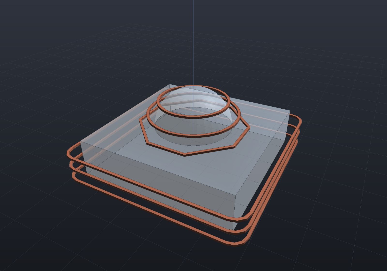
// The ball-nose riding its raster rows over the dome — the tool part's tip is at its// origin, so following the pass points puts the tip on the cutter-location surface.var part = Shape.Box(24, 24, 6) | Shape.Sphere(6).Translate(0, 0, 3);var ball = new MillTool(Diameter: 4);var raster = CncSurfacing.Raster(part, ball, sampleStep: 1);
var scene = new Scene();scene.Add(new Part("part", part, Palette.Steel));// The shank is slimmer than the ball on purpose: an equal-radius coaxial shank is// tangent to the sphere along its equator, exactly the coincident curved input the// B-Rep boolean refuses by name.scene.Add(new Part("ball",    Shape.Sphere(2).Translate(0, 0, 2) | Shape.Cylinder(1.4, 9).Translate(0, 0, 6.5),    Palette.Coral));
// A handful of rows across the dome keeps the motion legible at 36 frames.var rows = raster.Passes.Skip(raster.Passes.Count / 2 - 3).Take(6);var waypoints = rows.SelectMany(p => p.Points).ToList();var animation = new Animation(durationSeconds: 6)    .With(PathTracks.Follow(scene, "ball", waypoints));
The accuracy split is stated rather than averaged: a raster tip is exact to the trace tolerance everywhere (a flat top reads the face’s own height to 1e-6; the dome apex is touched at its own height, because the global grid anchors a sample at exactly (0, 0)); a waterline point is exact where the wall is steep — the case waterline is for — and honest to the marching-squares crossing error where the contour crosses a near-horizontal region, where no in-plane direction changes the field. Where the field is a correct-sign lower bound (a CSG difference near its subtracted tool’s fictitious faces), the r-isolevel lies farther from the part than the true offset — stock left, never a gouge: the conservative direction, inherited from the field contract rather than arranged.
Passes are in the shape’s own coordinates (the G-code z word is the tool tip, the
machining convention), and the writer is the stage-2 CncGcodeWriter unchanged — a move’s
meaning is its shape, so an XYZ-combined raster move cuts at the feed rate with nothing new.
Flat and bull-nose cutters
Raster takes a MillCutter — ball-nose, flat end, or bull-nose — and the routing records an
overturned prediction: the backlog filed flat/bull as “the rounded-cone distance the SDF
vocabulary already spells”, and it does not survive contact with the arithmetic. A
flat-bottomed tool’s cutter-location condition is a minimum over its disc of the field, and
certifying a minimum to ε through a 1-Lipschitz oracle takes Ω((a/ε)²) evaluations wherever
the field is horizontally flat — which is not the hostile case but the common one (every
plateau a flat cutter exists to finish). The ball is special precisely because its disc is a
point. So flat and bull-nose ride the tessellation with per-mode contact arithmetic — the
textbook drop-cutter: a vertex lifts the tip by the bottom profile exactly, an edge maximizes
over a bracketed 1D scan (a torus–line tangency is a quartic), a face’s contact is closed
form (ρ* = a + r·s/√(1+s²)) — while a ball-nose cutter keeps the exact implicit route
byte-for-byte.
var dome = Shape.Sphere(10);var tool = new MillTool(8, StepDown: 2);var flat = CncSurfacing.Raster(dome, tool, cutter: MillCutter.FlatEnd(8));var ball = CncSurfacing.Raster(dome, tool);double At(MillOperation op, double x) => op.Passes .SelectMany(p => p.Points).First(p => Math.Abs(p.X - x) < 1e-9 && p.Y == 0).Z;// The flat spot: with the apex under the disc the tip sits AT the apex — exactly —// where a ball rolls off. Past the disc the rim rides the dome (the APT closed form).Console.WriteLine($"over the apex offset 2: flat {At(flat, 2):0.####} ball {At(ball, 2):0.####}");Console.WriteLine($"rim contact at 6: {At(flat, 6):0.####} vs closed form " + $"{Math.Sqrt(100 - 2 * 2):0.####} (inscribed mesh: low, never high)");The oracles are equalities where the geometry makes them possible: the apex vertex sits under
the flat disc where the bottom profile is exactly zero, so the flat spot is z == S
exactly; a flat plate reads its own top exactly out to one disc radius past the edge (the
edge mode); and a ball pushed through the mesh route agrees with the exact field route to
the chord error — two constructions of one surface checking each other, with the band
honestly slope-amplified near the silhouette (dz/dd diverges there). Waterline carries them
too, as the silhouette-dilation contour: at each tip level the collision region is the
part’s XY silhouette above the tip plane dilated by the tool — exact against the mesh for a
flat cutter (the disc collides with exactly the material above its own plane within R) — and
for a bull-nose a banded conservative ladder: the corner torus’s reach grows with height
above the tip, so band k clips the mesh above z + r·k/K and grows by the band’s outer
reach, over-covering its own slice — the contour stands off at least the true CL distance,
stock never gouge. On a 45° cone the three-sided oracle separates the answers: the banded
standoff addend measures its own closed form 3.661 (Ø8 r1, K = 4), above the exact
a + r(√2 − 1) = 3.414 and measurably under the sharp envelope’s 4.0.
Raster rows run along a stated rasterAngleDegrees (both cutter routes, one grid rule):
the grid anchors in the rotated frame — the phase rule, a pattern being a function of
the stated spacing and angle, never of where the part sits — and a quarter turn is exact
(a sign swap, never a cos), so a 90° raster is the transposed grid to the last bit.
Raster rows link without a retract (linkRows: true, both cutter routes through the
one serpentine rule): the rows merge into one pass, the connecting stretch between a row’s
end and the next row’s start sampled on the cutter-location surface through the same
drop — the link carries exactly the fidelity a within-row chord does, and one plunge
replaces one per row.
Adaptive stepover (AdaptiveRaster)
A uniform raster keeps the row spacing constant, so the scallop grows wherever the
surface tilts — the CL points spread apart on the surface by 1/cos θ. AdaptiveRaster
inverts that: the scallop height is the stated number, and each next row is placed by
bisection on the measured worst 3D distance between corresponding CL points of the row
pair, through the same chord identity ScallopHeight states. On a plane tilted by θ the
chord between CL points IS the surface distance, so the spacing lands on exactly
cos θ times the flat spacing — a closed form the tests hold at 45° — and on curved
surfaces the chord is first-order (an under-estimate on convex, over on concave), stated
rather than hidden.
The governing radius is the corner radius (a ball’s is its own radius): the cusp between passes is cut by the corner torus, so a bull-nose adapts on its corner and a flat cutter — which leaves facets, not scallops — refuses by name. Rows anchor to the part, not the global grid: the phase rule deliberately does not apply, because a variable spacing has no stated number to be a function of. At a cliff the spacing floors at 1/32 of the flat spacing and moves on — a wall’s CL distance is dominated by the drop, so no stepover rule can meet the target there; the wall’s finish belongs to the flank.
var ramp = Shape.Extrude( Sketch.Polygon([new(-15, 0), new(15, 0), new(-15, 30)]), 40).RotateY(-Math.PI / 2);var op = CncSurfacing.AdaptiveRaster(ramp, new MillTool(6), scallopHeight: 0.05, sampleStep: 2);double flat = CncSurfacing.StepoverForScallop(3, 0.05);var ys = op.Passes.Select(p => p.Points[0].Y).ToList();var slopePairs = Enumerable.Range(1, ys.Count - 1) .Where(i => ys[i - 1] > 5 && ys[i] < 20) .Select(i => ys[i] - ys[i - 1]).ToList();Console.WriteLine($"flat spacing {flat:0.####}; on the 45-degree slope " + $"{slopePairs.Average():0.####} ~= flat*cos45 = {flat * Math.Cos(Math.PI / 4):0.####}");Console.WriteLine($"{ys.Count} rows over the ramp against " + $"{(int)Math.Ceiling(36 / flat) + 1} a uniform raster at the same scallop would need " + "everywhere the slope demands");Holder collision (CncHolder)
The holder is modelled as a flat disc of the holder diameter whose bottom rides
StickoutLength above the tool tip — the conservative envelope of any real tapered holder
— so a pass point collides exactly when the surface under the disc reaches above
cl.z + stickout, which is the flat drop-cutter question at the holder’s own radius:
the check rides the same vertex/edge/face contact arithmetic the flat cutter rides, so the
holder check and the flat cutter cannot disagree about what a disc touches.
The deliverable is MinimumStickout — the smallest stickout that clears every pass point
— and at exactly that stickout the setup passes (zero clearance is resting contact,
not a collision). The check runs against the finished part, stated rather than hidden:
in-process stock is more material, so it is exact for finishing passes (where holder
collisions live) and a lower bound for roughing.
var part = Shape.Box(100, 60, 6).Translate(0, 0, -3) .Union(Shape.Box(10, 10, 12).Translate(20, 0, 6));var finish = CncSurfacing.Raster(part, new MillTool(6), sampleStep: 2);var report = CncHolder.Check(part, finish, new ToolHolder(Diameter: 20, StickoutLength: 8));Console.WriteLine($"stickout 8: {report.Collisions.Count} collisions, " + $"minimum stickout {report.MinimumStickout:0.######}");Console.WriteLine($"worst deficit {report.Collisions.Max(c => c.Deficit):0.###} " + "(how far the disc reaches into the part)");var fixedUp = CncHolder.Check(part, finish, new ToolHolder(20, report.MinimumStickout));Console.WriteLine($"at the reported minimum: {(fixedUp.Ok ? "clear" : "still colliding")}");One number in that fixture is worth knowing about: the raster runs one grid step past the
part bounds, and there the ball’s CL dips below the top face as it wraps the outer edge
(exactly √(r² − d²) − r, −1 at a corner sampled √5 away in XY) — so a boss that a rim
point’s disc can reach adds that dip to the minimum stickout, and the honest closed form
stops being the obstacle height. Real setup arithmetic, and exactly the kind a machinist
eyeballing “boss height plus a bit” misses the same way.
Not in stage 3: HSM adaptive clearing (stage 4). Rest machining landed on the milling page; the flat/bull waterline above landed as the silhouette-dilation contour.