MID / LDS — routing on a moulded surface
The flagship of the ECAD campaign: routing conductors and seating components on a moulded, doubly-curved surface rather than a flat board — the MID (moulded interconnect device) / LDS (laser direct structuring) construction, where a plastic housing carries its own circuit on its shaped wall.
It works on any surface — a torus, a bumpy blob, a whole closed shell — not one exp-map chart. A
MidSurface wraps an arbitrary triangle mesh and answers the
three questions the routing asks intrinsically: where the nearest surface point is (a pad states its
world position and snaps to the shell), what tangent frame sits there (a component poses on the
surface), and what the surface does locally — a small exponential-map chart around a point, the
geodesic-distance approximator the DRC measures a clearance in and reads the distortion from. No
feature depends on a chart covering the whole part; every chart is local and per query, so a closed
surface that a single global exp map would wrap onto itself is routed with no chart at all.
The showcase: a moulded wearable
A wide, low ellipsoidal wearable dome — a moulded pebble — carrying its own circuit: an MCU, two
LEDs, a connector and passives seated on the shaped surface, wired by conductors the board
routes itself as geodesics along the dome. Pads are placed and MidRouting.Route lays a DRC-clean
geodesic per net; the whole layout is verified on the surface — every net connects its pads and the 3D
DRC is clean — before it is rendered.
// The moulded shell: a wide, low ellipsoidal dome (a wearable puck), genuinely doubly-curved so no// single exp-map chart is an isometry — exactly what the intrinsic model exists for.double R = 10; var scale = new Vector3d(1.5, 1.5, 0.62);var shell = MeshPrimitives.UvSphere(R, 200, 100).Transformed(Matrix4d.CreateScale(scale));var board = MidBoard.OnMesh(shell);              // INTRINSIC: no seed, no radius, works on any geometry
// A dome surface point above a footprint (x, y) — "place this here on the wearable's top".Vector3d Above(double x, double y) {    double rx = R * scale.X, rz = R * scale.Z;    double z = rz * Math.Sqrt(Math.Max(1 - (x * x + y * y) / (rx * rx), 0));    return new Vector3d(x, y, z + 0.01);}
// Small electronic-component bodies, modeled +Z out of the surface with the seating datum at the// origin, so the seat convention drops them onto the dome pointing outward.Shape Qfn()       => Shape.Box(5, 5, 1.1).Translate(new Vector3d(0, 0, 0.55));Shape Connector() => Shape.Box(6, 3.2, 2.6).Translate(new Vector3d(0, 0, 1.3));Shape Led()       => Shape.Cylinder(1.0, 0.7).Translate(new Vector3d(0, 0, 0.35))                         .Union(Shape.Sphere(1.0).Scale(1, 1, 0.7).Translate(new Vector3d(0, 0, 0.7)));Shape Passive()   => Shape.Box(1.6, 0.8, 0.45).Translate(new Vector3d(0, 0, 0.225));
// Seat the components on the surface (Z = surface normal), each snapped to the dome. The whole scene// is displayed offset from the origin so the world axis gizmo stays out of the composition.var chip = new PartColor(0.16f, 0.18f, 0.22f);var dark = new PartColor(0.24f, 0.26f, 0.30f);var brown = new PartColor(0.35f, 0.30f, 0.26f);var move = Matrix4d.CreateTranslation(new Vector3d(0, 24, 0));Part P(string name, Shape s, PartColor c) => new(name, s, c, move);var scene = new Scene();scene.Add(new Part("shell", shell, new PartColor(0.30f, 0.55f, 0.62f), move));scene.Add(P("mcu",   board.Seat(Qfn(),       Above(0, 0)).Body,        chip));scene.Add(P("conn",  board.Seat(Connector(), Above(0, -9.5)).Body,     dark));scene.Add(P("led1",  board.Seat(Led(),       Above(-9.5, 2.5)).Body,   Palette.Coral));scene.Add(P("led2",  board.Seat(Led(),       Above(9.5, 2.5)).Body,    Palette.Sky));scene.Add(P("r1",    board.Seat(Passive(),   Above(-2.6, 4.8)).Body,   brown));scene.Add(P("r2",    board.Seat(Passive(),   Above(0, 5.2)).Body,      brown));scene.Add(P("r3",    board.Seat(Passive(),   Above(2.6, 4.8)).Body,    brown));
// Pads for four nets, radiating from the central MCU: connector power/ground to the MCU's south pads,// and each LED to a side pad.var nets = new[] {    ("5V",  Above(-1.7, -9.0), Above(-1.7, -3.2)),    ("GND", Above( 1.7, -9.0), Above( 1.7, -3.2)),    ("D1",  Above(-3.2,  0.9), Above(-8.8,  2.5)),    ("D2",  Above( 3.2,  0.9), Above( 8.8,  2.5)),};foreach (var (net, a, b) in nets) {    board.PlacePad(net, a, 0.6, $"{net}.a");    board.PlacePad(net, b, 0.6, $"{net}.b");}
// AUTO-ROUTE: the board routes itself — a DRC-aware geodesic per net over the mesh vertex graph, each// committed only after the exact 3D DRC certifies it clean. A net it cannot route is reported by name.var routed = MidRouting.Route(board, null, new SurfaceRouteOptions { TraceWidth = 0.35 });Console.WriteLine($"auto-routed {routed.RoutedNets.Count} nets: {routed}");if (!routed.FullyRouted)    throw new Exception("the wearable did not fully route: " + routed);foreach (var trace in routed.Traces)    scene.Add(P($"copper-{trace.Net}", trace.Conductor(0.06), Palette.Brass));
// Verify on the surface: every routed net connects its pads, the 3D DRC is clean. Self-checking, so// this example cannot rot.var report = MidRouting.Verify(board);Console.WriteLine($"nets connected: {report.Ratsnest.Count == 0}; DRC ok: {report.Ok}");if (!report.Ok || report.Ratsnest.Count != 0)    throw new Exception("the wearable did not verify: " + report);
var camera = new CameraState(-Math.PI / 2 + 0.5, 0.66, 50, (0, 23, 3.4));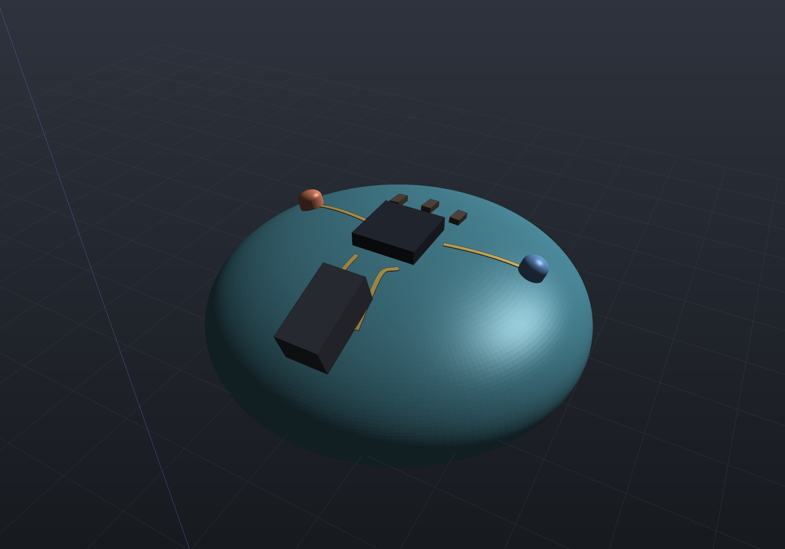
The surface auto-router
MidRouting.Route is the geodesic analogue of the flat autorouter (PcbRouter):
it turns the ratsnest of an intrinsic board into DRC-clean copper. Each unrouted net is decomposed into
2-pin connections over an MST and routed as a DRC-aware geodesic maze search over the mesh vertex
graph (edge weight the geodesic edge length, an A* whose 3D-straight-line heuristic is admissible
because a chord never exceeds a geodesic), then straightened.
var board = MidBoard.OnMesh(shell); // an INTRINSIC board (OnMesh, any geometry)// ... place the pads carrying each net ...var result = MidRouting.Route(board, rules, new SurfaceRouteOptions { TraceWidth = 0.35 });// result.RoutedNets / result.UnroutedNets / result.Traces / result.RipUpsThe verification bar is the flat router’s, lifted onto the surface — an autorouter that connects while violating clearance is the classic silent failure, so the router is built so that cannot happen:
- The mesh vertex graph is an accelerator; the exact 3D DRC is the source of truth. A candidate
geodesic is committed only after
Mid3dDrc.RouteCandidateClearscertifies it adds no violation (and anUncertainpair — one the surface cannot certify — is treated as not passable), so a graph-resolution error can never ship a clearance-violating trace, and the partial result of a board it cannot fully route is still clean. - A net that cannot be routed cleanly is reported UNROUTABLE by name — never a silent violation.
- Rip-up-and-reroute for congestion, exactly the flat router’s negotiated-congestion doctrine: a net with no clean geodesic routes across the committed traces that block it (soft obstacles, a per-net bitmask; pads and the mesh boundary are hard), rips those up, re-routes cleanly without them, and re-queues them — bounded, so a truly boxed-in net terminates and is named.
Because the exact DRC decides every commit, the search’s obstacle model can safely over-block: a vertex is blocked when laying the net’s copper there comes within the clearance of an other-net feature, measured as the 3D chord (a lower bound on the geodesic), plus half a longest edge so the raw edge-graph path is DRC-clean by construction. Over-blocking only costs a detour or a named refusal, never correctness.
The certified geodesic DRC
On an intrinsic board the clearance between two different-net conductors is a geodesic surface distance, measured on the mesh. Two certified facts make the three-valued verdict honest:
- A 3D chord is never longer than a surface geodesic, so a chord edge-to-edge distance at or above the clearance proves the surface clearance whatever the curvature — the broad phase, and the reason a pair on the far side of the dome is certified Clear with no chart at all.
- A closer pair is measured tightly in a local exp-map chart built around it (the geodesic-distance approximator, exact on a developable patch) with the same grow-and-intersect the flat copper DRC uses and the local distortion folded in.
The result is three-valued: Clear, Violation, or Uncertain — where the distortion band straddles the limit (the clearance is comparable to the curvature radius) or the curvature is too high to cover the pair in a chart, the pair is refused, not passed false-precise (the near-tangency rule the anti-drill tamper mesh refuses conformal placement over). A plane never straddles; a small sphere with a clearance a large fraction of its radius does — and the DRC says so rather than guessing.
Exact where one chart applies — the developable oracle
Where a single chart is an isometry — a flat or developable patch (a cylinder, a cone) —
MidBoard.OnSurface authors features in one exp map’s (u, v),
which is the intrinsic geodesic exactly. The decisive test builds a cylindrical MID board and the
flat unrolled sheet, routes the same nets on both, and asserts the verdicts and measured
separations agree — bit for bit.
// A finely tessellated CYLINDER WALL (a developable moulded surface), and a flat unrolled sheet.HalfEdgeMesh Tube(double r, double h, int around, int along) {    var pos = new List<Vector3d>();    for (int j = 0; j <= along; j++)        for (int i = 0; i < around; i++) {            double a = 2 * Math.PI * i / around;            pos.Add(new Vector3d(r * Math.Cos(a), r * Math.Sin(a), h * j / along));        }    var faces = new List<int[]>();    for (int j = 0; j < along; j++)        for (int i = 0; i < around; i++) {            int p = j * around + i, q = j * around + (i + 1) % around;            faces.Add(new[] { p, q, q + around });            faces.Add(new[] { p, q + around, p + around });        }    return HalfEdgeMesh.Build(pos, faces);}HalfEdgeMesh Plane(int n, double size) {    var pos = new List<Vector3d>();    for (int j = 0; j <= n; j++) for (int i = 0; i <= n; i++)        pos.Add(new Vector3d(-size / 2 + size * i / n, -size / 2 + size * j / n, 0));    var faces = new List<int[]>();    for (int j = 0; j < n; j++) for (int i = 0; i < n; i++) {        int a = j * (n + 1) + i;        faces.Add(new[] { a, a + 1, a + n + 2 });        faces.Add(new[] { a, a + n + 2, a + n + 1 });    }    return HalfEdgeMesh.Build(pos, faces);}
var tube = Tube(6, 8, 64, 40);var plane = Plane(40, 8);
// Parameterize each surface by the exp map from a stated origin — the routing PATCH, a real design// parameter (which part of the moulding carries the circuit).var cylinder = MidBoard.OnSurface(tube, seedVertex: 20 * 64, referenceDirection: Vector3d.UnitY, radius: 2.5);var flat     = MidBoard.OnSurface(plane, seedVertex: 20 * 41 + 20, referenceDirection: Vector3d.UnitX, radius: 5.0);Console.WriteLine($"cylinder exp-map distortion: {cylinder.MaxDistortion:E2}  (developable => tiny)");Console.WriteLine($"plane exp-map distortion:    {flat.MaxDistortion:E2}  (the identity)");
// Route the SAME nets in exp-map (u, v) coordinates on both surfaces.void Route(MidBoard b) {    b.PlacePad("A", new Vector2d(0, 0), 0.3, "A");    b.PlacePad("B", new Vector2d(0.30 + 0.30, 0), 0.3, "B");   // 0.30 mm edge-to-edge gap: clear    b.PlacePad("C", new Vector2d(0, 1), 0.3, "C");    b.PlacePad("D", new Vector2d(0.30 + 0.05, 1), 0.3, "D");   // 0.05 mm gap: too close}Route(cylinder);Route(flat);
var rules = DrcRuleSet.Default;               // 0.15 mm clearancevar on3d = Mid3dDrc.Check(cylinder, rules);   // the 3D DRC on the moulded cylindervar on2d = Mid3dDrc.Check(flat, rules);       // the unrolled 2D DRC on the flat sheet
Console.WriteLine($"3D DRC on the cylinder: {on3d.Violations.Count} violation(s), {on3d.Uncertain.Count} uncertain");Console.WriteLine($"unrolled 2D DRC:        {on2d.Violations.Count} violation(s), {on2d.Uncertain.Count} uncertain");var v3 = on3d.Violations.Single();var v2 = on2d.Violations.Single();Console.WriteLine($"same verdict ({v3.Rule}), same measured separation: "    + $"{v3.MeasuredParameter:R} == {v2.MeasuredParameter:R}  (bit for bit)");Console.WriteLine($"the cylinder folds the distortion into the surface clearance: "    + $"[{v3.SurfaceSeparationMin:g4}, {v3.SurfaceSeparationMax:g4}] mm");
The verdicts and the measured (u, v) separations are identical because both run the same
grow-and-intersect on the same (u, v) geometry; the only thing the cylinder adds is the surface
clearance band the fold reports, which on a developable surface is a hair wide. The intrinsic
board reaches the same answer on a cylinder to the discretisation grade — the developable oracle under
the general formulation.
Conductors lifted onto the moulded surface
A SurfaceTrace is a centre-line lifted onto the surface, so its endpoints land exactly on the pad
points it connects. On an intrinsic board it is a geodesic path on the mesh
(MidRouting.Connect uses DijkstraGraphDistance’s edge-graph
geodesic), so a straight (u, v) line does not cut through a curved shell; on a global-chart board it
is the straight (u, v) line, which on a developable patch is the geodesic. Its exported form
(Conductor) is a thin conductive Shape — a ribbon offset in the surface tangent plane and extruded
along the surface normal — that round-trips through STL / STEP like any part, and each trace reports
the distortion it carried (MinScale, MaxScale).
HalfEdgeMesh Tube(double r, double h, int around, int along) {    var pos = new List<Vector3d>();    for (int j = 0; j <= along; j++)        for (int i = 0; i < around; i++) {            double a = 2 * Math.PI * i / around;            pos.Add(new Vector3d(r * Math.Cos(a), r * Math.Sin(a), h * j / along));        }    var faces = new List<int[]>();    for (int j = 0; j < along; j++)        for (int i = 0; i < around; i++) {            int p = j * around + i, q = j * around + (i + 1) % around;            faces.Add(new[] { p, q, q + around });            faces.Add(new[] { p, q + around, p + around });        }    return HalfEdgeMesh.Build(pos, faces);}
var tube = Tube(8, 14, 96, 60);// The map radius is a GRAPH distance (it over-estimates the straight-line one), so state it// comfortably above the furthest feature's reach.var board = MidBoard.OnSurface(tube, seedVertex: 30 * 96, referenceDirection: Vector3d.UnitY, radius: 9.0);
// A serpentine and two straight conductors, routed in (u, v) and lifted onto the curved wall.var serpentine = board.PlaceTrace("SIG", new[] {    new Vector2d(-4, -3), new Vector2d(-4, 3), new Vector2d(-2.5, 3),    new Vector2d(-2.5, -3), new Vector2d(-1, -3), new Vector2d(-1, 3) }, 0.6, "S");var vcc = board.PlaceTrace("VCC", new[] { new Vector2d(1.5, -3), new Vector2d(1.5, 3) }, 0.6, "V");var gnd = board.PlaceTrace("GND", new[] { new Vector2d(3, -3), new Vector2d(3, 3) }, 0.6, "G");
var scene = new Scene();scene.Add(new Part("wall", Shape.From(tube), Palette.Steel));scene.Add(new Part("SIG", serpentine.Conductor(0.25), Palette.Coral));scene.Add(new Part("VCC", vcc.Conductor(0.25), Palette.Teal));scene.Add(new Part("GND", gnd.Conductor(0.25), Palette.Plum));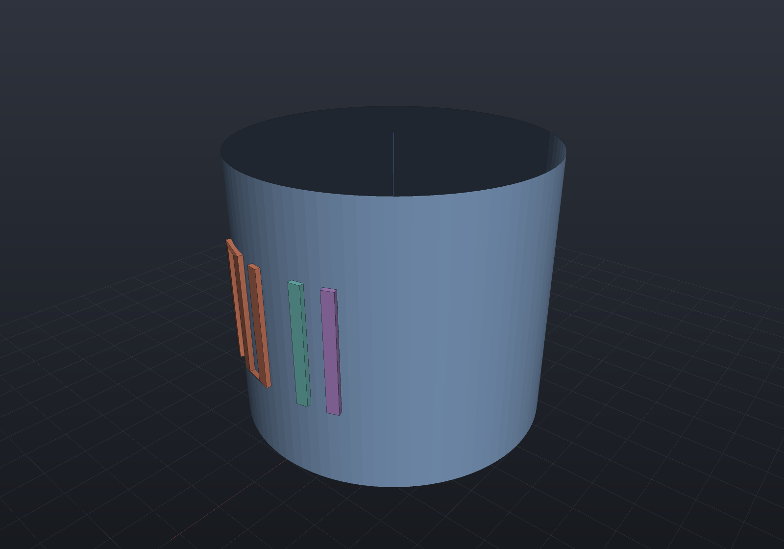
Seating a component
A catalogue HardwareComponent — or a raw Shape body (an MCU, an LED, a connector modelled as a
small solid) — seats on the surface at a world position, its body posed in the surface’s own tangent
frame (Z the surface normal), on any geometry:
var board = MidBoard.OnMesh(mesh);var located = board.Locate(worldPoint); // snap to the surfacevar seated = board.Seat(StandardComponents.CapScrew(6, 12), worldPoint);var chip = board.Seat(Shape.Box(5, 5, 1), worldPoint); // a raw electronic-component body// seated.Body is the component posed on the surface, ready to be an assembly occurrence.The global-chart board seats by (u, v) instead (board.Seat(component, new Vector2d(u, v))).
Multi-shell — an inner moulded copper layer
A real LDS part carries copper on the outer moulded wall and on an inner shell, stitched by
through-shell vias. MidStack is that board — an outer MidBoard plus one or more inner shells, each
the outer mesh with every vertex offset inward by a dielectric thickness along its angle-weighted
vertex normal (the MeshSdf / boundary-layer pseudonormal convention — never a raw face normal, which
would tear a shared vertex).
The inner shell keeps the same mesh topology, and that is the load-bearing decision. A surface point
on the outer shell (a face + barycentric weights) has a corresponding point on the inner shell (the
same face + weights, on the offset mesh), so a through-shell SurfaceVia is exactly “tie the outer point
to its corresponding inner point”. Each shell is its own MidBoard with its own exp-map
machinery — an inner shell’s geodesic distances differ from the outer’s, because offsetting a curved
surface changes them — so the existing single-surface placement, routing and DRC run per shell
unchanged: place a pad, trace or component by placing it on stack.Shell(k) (or stack.Outer /
stack.Inner).
HalfEdgeMesh Tube(double rr, double h, int around, int along) {    var pos = new List<Vector3d>();    for (int j = 0; j <= along; j++)        for (int i = 0; i < around; i++) {            double a = 2 * Math.PI * i / around;            pos.Add(new Vector3d(rr * Math.Cos(a), rr * Math.Sin(a), h * j / along));        }    var faces = new List<int[]>();    for (int j = 0; j < along; j++)        for (int i = 0; i < around; i++) {            int p = j * around + i, q = j * around + (i + 1) % around;            faces.Add(new[] { p, q, q + around });            faces.Add(new[] { p, q + around, p + around });        }    return HalfEdgeMesh.Build(pos, faces);}
double r = 8, t = 0.8;// A moulded CYLINDER WALL plus an inner shell offset inward by the dielectric thickness t. On a// developable surface the inward normal offset is EXACT: the inner shell is a concentric cylinder r − t.var stack = MidStack.TwoShell(Tube(r, 14, 96, 60), t);double ir = r - t;Vector3d Out(double a, double z) => new(r * Math.Cos(a), r * Math.Sin(a), z);Vector3d In(double a, double z) => new(ir * Math.Cos(a), ir * Math.Sin(a), z);
// OUTER shell: a SIG net up to the via foot, and a separate GND rail beside it.var sigA = stack.Outer.PlacePad("SIG", Out(0, 3), 0.7, "SIG.a");var viaWorld = Out(0, 10.5);var sigVia = stack.Outer.PlacePad("SIG", viaWorld, 0.7, "SIG.via");var outerSig = MidRouting.Connect(stack.Outer, sigA, sigVia, 0.5);var gndA = stack.Outer.PlacePad("GND", Out(0.55, 3), 0.7, "GND.a");var gndB = stack.Outer.PlacePad("GND", Out(0.55, 11), 0.7, "GND.b");var outerGnd = MidRouting.Connect(stack.Outer, gndA, gndB, 0.5);
// A through-shell VIA stitches SIG to the inner shell at the corresponding point.var via = stack.AddVia("SIG", viaWorld, 0.6);
// INNER shell: SIG continues from the via foot around to a sink pad.var inVia = stack.Inner.PlacePad("SIG", via.InnerPoint, 0.7, "SIG.via.in");var inSink = stack.Inner.PlacePad("SIG", In(1.5, 3), 0.7, "SIG.sink");var innerSig = MidRouting.Connect(stack.Inner, inVia, inSink, 0.5);
// Verify: SIG connects across BOTH shells through the via, and the 3D DRC is clean. Self-checking.var report = stack.Check();if (report.Ratsnest.Count != 0 || !report.Ok)    throw new Exception("the multi-shell board did not verify: " + report);
var scene = new Scene();scene.Add(new Part("outer wall", Shape.From(stack.Outer.Mesh), Palette.Steel) { DisplayMode = DisplayMode.Translucent });scene.Add(new Part("inner shell", Shape.From(stack.Inner.Mesh), new PartColor(0.42f, 0.48f, 0.54f)) { DisplayMode = DisplayMode.Translucent });scene.Add(new Part("SIG (outer)", outerSig.Conductor(0.2), Palette.Brass));scene.Add(new Part("GND (outer)", outerGnd.Conductor(0.2), Palette.Plum));scene.Add(new Part("SIG (inner)", innerSig.Conductor(0.2), Palette.Teal));scene.Add(new Part("via", via.Barrel(0.6), Palette.Coral));var camera = new CameraState(-Math.PI / 2 + 0.85, 0.42, 52, (0, 0, 7));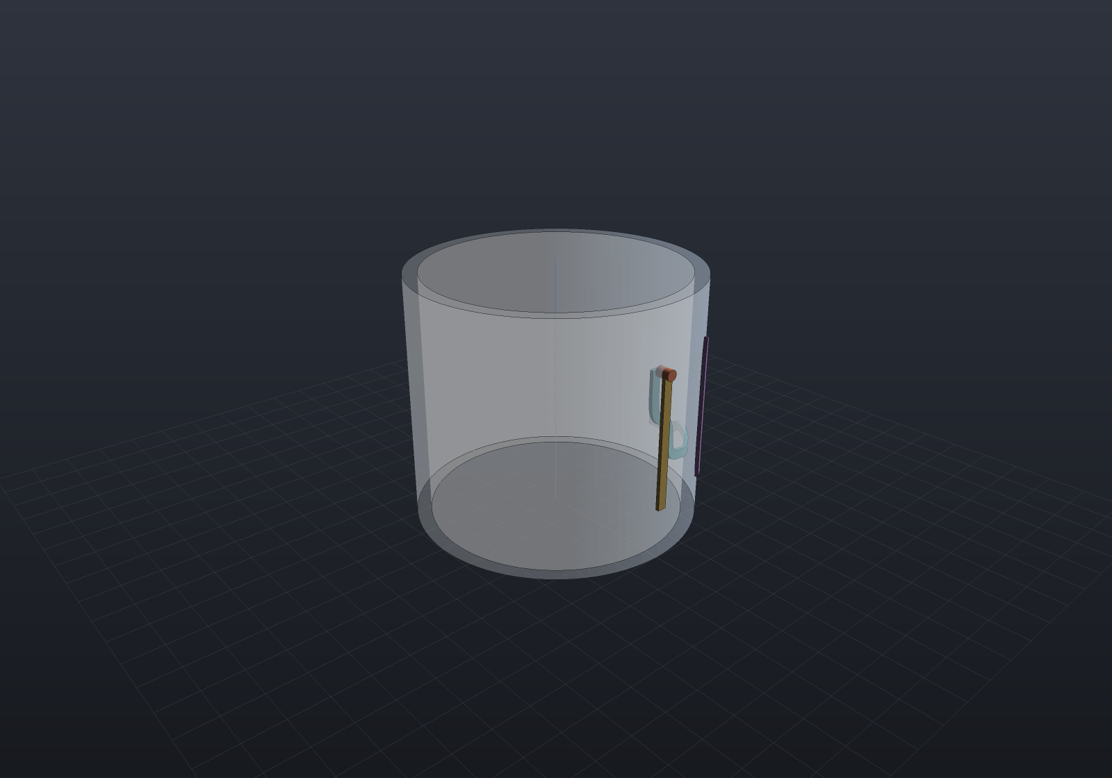
Connectivity and the DRC span the shells. Each shell’s copper is joined by the existing per-surface
touch rule, and a via joins its own pads across shells (the plated barrel), so stack.Connectivity()
answers the crux: a net whose copper lies on two shells is one connected net iff a via of that net ties
them (the PcbConnectivity cross-layer rule, lifted to surfaces). Remove the via and the two shells’
same-named copper are a cross-shell ratsnest. stack.Check() runs each shell’s same-shell clearance /
width DRC — a via’s clearance to other-net copper on both shells it touches falls out of that, since a
via pad is copper on its shell — plus the inter-shell via-to-via spacing rule. A single-shell
stack (no vias) reduces to a plain MidBoard, so its DRC is bit-identical to
Mid3dDrc.Check(board).
The developable oracle is preserved and made exact. On a cylinder the inward normal offset is an
isometry, so the inner shell is a concentric cylinder of radius r − t to round-off — the
angle-weighted vertex normal is exactly radial by symmetry, even at the free rim. An inward offset
self-intersects only where the surface is convex and t exceeds the local curvature radius (a
concave region offset inward merely diverges); a sphere offset inward past its radius turns inside out
and is refused by name (the offset’s signed volume flips sign), as is a developable inversion (an
offset triangle folds through itself).
Cross-shell auto-routing
MidRouting.Route(stack, …) auto-routes a two-shell stack — the surface analogue of the flat PCB
router’s layer-changing via. A net whose pads are on different shells, or that must hop to the
other shell to pass an obstacle, is routed over the union of both shells’ vertex graphs plus via
edges tying corresponding vertices across the dielectric; where the chosen path uses a via edge, a
through-shell SurfaceVia is placed there and the route splits into per-shell traces.
HalfEdgeMesh Tube(double rr, double h, int around, int along) {    var pos = new List<Vector3d>();    for (int j = 0; j <= along; j++)        for (int i = 0; i < around; i++) {            double a = 2 * Math.PI * i / around;            pos.Add(new Vector3d(rr * Math.Cos(a), rr * Math.Sin(a), h * j / along));        }    var faces = new List<int[]>();    for (int j = 0; j < along; j++)        for (int i = 0; i < around; i++) {            int p = j * around + i, q = j * around + (i + 1) % around;            faces.Add(new[] { p, q, q + around });            faces.Add(new[] { p, q + around, p + around });        }    return HalfEdgeMesh.Build(pos, faces);}
double r = 8, t = 0.9;var stack = MidStack.TwoShell(Tube(r, 14, 96, 60), t);double ir = r - t;Vector3d Out(double a, double z) => new(r * Math.Cos(a), r * Math.Sin(a), z);Vector3d In(double a, double z) => new(ir * Math.Cos(a), ir * Math.Sin(a), z);
// A cross-shell SIG net (an OUTER pad and an INNER pad) and a GND net on the outer shell SIG must clear.stack.Outer.PlacePad("SIG", Out(0, 3), 0.7, "SIG.out");stack.Inner.PlacePad("SIG", In(1.4, 11), 0.7, "SIG.in");stack.Outer.PlacePad("GND", Out(0.7, 3), 0.7, "GND.a");stack.Outer.PlacePad("GND", Out(0.7, 11), 0.7, "GND.b");
// AUTO-ROUTE the stack: the router chooses which shell each segment rides and drops the through-shell via.var rules = DrcRuleSet.Default with { MinCopperClearance = 0.4, MinTraceWidth = 0.25 };var result = MidRouting.Route(stack, rules, new SurfaceRouteOptions { TraceWidth = 0.5, ViaPadDiameter = 0.7 });// Self-checking: both nets route, SIG connects across the shells through the via, and the DRC is clean.if (!result.FullyRouted || !stack.Connectivity().Of("SIG").IsConnected || !stack.Check(rules).Ok)    throw new Exception("the cross-shell auto-route did not verify: " + result);
var scene = new Scene();scene.Add(new Part("outer wall", Shape.From(stack.Outer.Mesh), Palette.Steel) { DisplayMode = DisplayMode.Translucent });scene.Add(new Part("inner shell", Shape.From(stack.Inner.Mesh), new PartColor(0.42f, 0.48f, 0.54f)) { DisplayMode = DisplayMode.Translucent });int ti = 0;foreach (var trace in result.Traces)    scene.Add(new Part($"trace{ti++}", trace.Conductor(0.2), trace.Net == "GND" ? Palette.Plum : Palette.Brass));int vi = 0;foreach (var via in result.Vias)    scene.Add(new Part($"via{vi++}", via.Barrel(0.7), Palette.Coral));var camera = new CameraState(-Math.PI / 2 + 0.85, 0.42, 52, (0, 0, 7));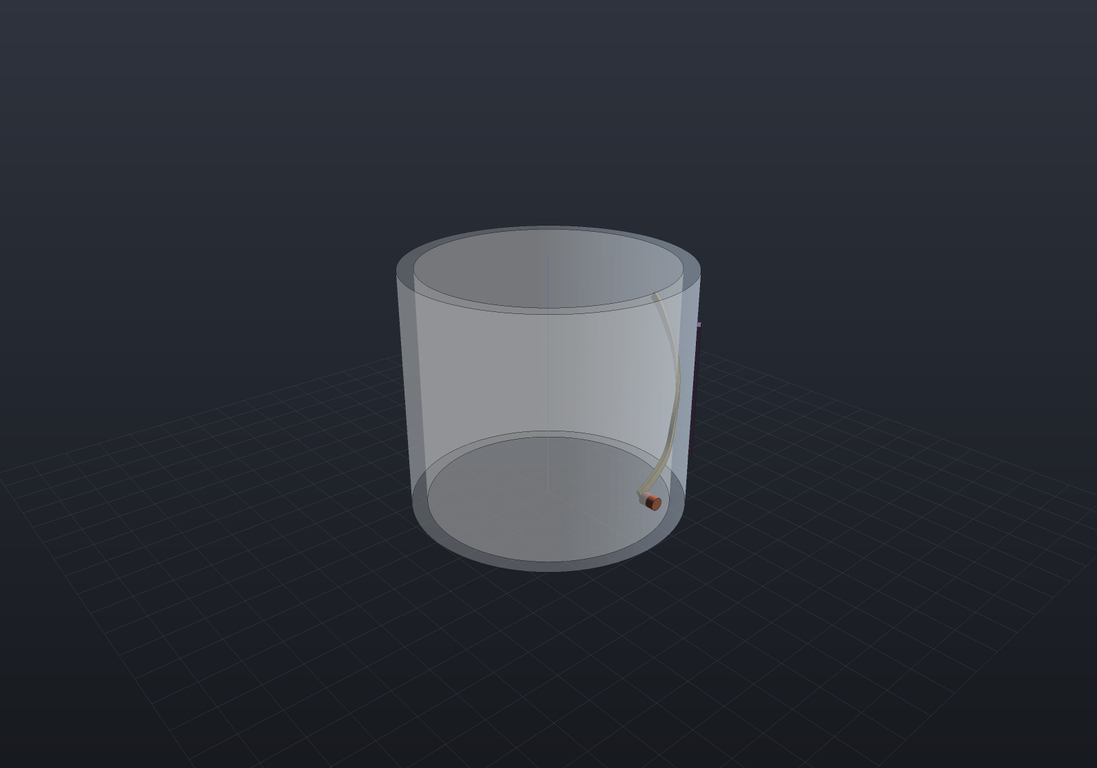
The combined graph. A node is (shell, vertex). A mesh edge on shell k connects two of that
shell’s vertices at that shell’s geodesic edge length; a via edge connects (k, v) to (k±1, v) —
trivial to enumerate because the shells share mesh topology, so vertex v corresponds across shells — at
a fixed via penalty, which biases the router toward staying on one shell unless a hop pays. The
straight-line heuristic stays admissible because every edge costs at least the 3D chord it spans (the via
penalty is at least the barrel chord). When the A* path uses a via edge, the router places a through-shell
via at that vertex (the existing AddVia machinery) and splits the route into per-shell surface traces —
so a same-shell net routes with no via at all, a net with pads on two shells with one, and
an obstacle hop with two (out and back).
The exact multi-shell DRC is the source of truth (the flat router’s own rule, lifted): a candidate
route + via is committed only after each per-shell trace CLEARS the existing other-net copper on its shell
(Mid3dDrc), each new via pad CLEARS other-net copper on every shell it touches, and the
inter-shell via-to-via web is met — so a graph-resolution error can never ship a clearance-violating
trace or via, and a partial result is still clean. Rip-up-and-reroute is the single-shell router’s
verbatim over the combined graph, so a net boxed in on both shells is reported UNROUTABLE by name.
A one-shell stack handed to this entry is refused, pointing at the single-shell
MidRouting.Route(stack.Outer, …); a > 2 shell stack is refused too, since it needs partial-span vias
(a via between two adjacent shells rather than the full-stack barrel AddVia places) — filed.
Scope, v1
MidRouting.Route auto-routes an intrinsic board and MidRouting.Connect places one trace
between two given pads; both lay geodesics on the mesh and both are certified by the same 3D DRC. The
auto-router runs on an intrinsic board (OnMesh); a global-chart board (OnSurface, kept for the
exact developable DRC oracle) is refused by name with a pointer to OnMesh. Multi-shell MID (copper
on an inner moulded shell as well as the outer, stitched by through-shell vias) has landed as MidStack
(see above), and cross-shell auto-routing — MidRouting.Route(stack, …), the layer-changing via on
surfaces — chooses which shell a net rides and places the vias (see above). Filed as later stages:
topological / shove routing on the surface (v1 detours around obstacles but does not push them),
optimal via minimisation (v1 uses a fixed via penalty) and partial-span vias for a > 2 shell
stack (v1 routes a two-shell stack with full-stack vias), length matching, and a conformal
solder mask / pour on the surface (refused for the distortion reason, exactly as copper pours already
refuse curved walls). LDS process specifics (laser activation paths) are out of scope.
Verification
The bar is higher than usual because ECAD fails plausibly. On any surface: a torus (a closed
surface a single global chart would wrap — measured MaxDistortion > 1) is routed and verified with no
chart; a sphere geodesic matches its great-circle closed form R·θ to the edge-graph discretisation
grade; a bumpy blob routes clean with its distortion reported per region; a pair on the far side is
certified Clear, a near pair a Violation, and a near-limit pair on a high-curvature patch
refused (Uncertain) while the same pair on a plane is certified. Where one chart applies: the
cylinder’s 3D DRC verdicts and measured separations equal the unrolled sheet’s, bit for bit. A
geodesic trace’s endpoints land exactly on their pads; the exported conductor is a closed solid
that round-trips through STL; the whole check is deterministic; and the showcase itself
self-verifies (its render throws if the nets do not route, connect or pass the DRC).
The auto-router clears the same bar: a 2-pin net on a cylinder and on a sphere cap routes clean and connected; several nets route around each other (a net’s copper detours where its straight geodesic would cross another’s); a congested board that a greedy pass leaves unrouted is completed by rip-up (both clean); a pin walled in by other-net copper is unroutable by name with the rest routed and clean; a dense knot’s partial result is always DRC-clean with the failures named; on a developable cylinder the routed connectivity matches the unrolled flat board’s (both clean, both fully routed — a search need not be bit-identical); and two runs are deterministic vertex for vertex.
Multi-shell (MidStack) clears its own bar. The decisive oracle is the developable one: a
cylinder’s inner shell is a concentric cylinder of radius r − t to round-off (worst vertex error
< 1e-11, the free rim included). Cross-shell connectivity is proved by the via mutation — a VOUT
pad on the outer shell and one on the inner, tied by a via, are one connected net; remove the via and
they split into a cross-shell ratsnest. The two-shell DRC finds a same-shell clearance violation on the
inner shell, finds a via too close to other-net copper on either shell, finds a via-to-via
spacing violation, and passes a well-spaced board clean; a single-shell stack’s DRC is bit-identical
to Mid3dDrc.Check; the self-intersection guard is refused by name on a sphere offset past its
radius; the via barrel is a closed solid; and the build is deterministic.
Cross-shell auto-routing clears the flat router’s bar on the surface. A cross-shell 2-pin net (an outer pad and an inner pad) routes with exactly one via, both per-shell segments clean and the net connected; a same-shell net with a clear path routes with no via (the via penalty keeps it on one shell); an obstacle hop — a net whose straight outer path is blocked by a full ring of other-net copper — routes through the inner shell with two vias, and the mutation that proves the cross-shell capability is what routed it is that the same fixture on a single shell is unroutable by name. Every committed route + via passes the exact multi-shell DRC; a pin walled in on both shells is unroutable by name with the rest routed and clean; a one-shell stack and a > 2 shell stack are refused by name; and two runs are deterministic vertex for vertex.