Drawings (hidden lines, sheets, dimensions)
A model becomes a drawing in three steps, and EngrCAD owns all three:
- Hidden-line removal (
HiddenLineRemoval) projects a scene’s edges into a view plane and classifies each piece visible or hidden. - A sheet (
DrawingSheet) places those views on paper with a border and a title block, at a standard scale, in first- or third-angle projection. - Export writes the sheet as SVG or DXF, with every line class on its own layer, so the file opens in a drafting package looking the way a drawing should — or as PDF, the format a drawing is actually sent in.
The result is a document you can send to a machinist.
A three-view sheet
DrawingSheet.StandardLayout builds the classic set — front, top, right and an
isometric — at one shared scale, chosen as the largest ISO 5455
ratio that fits the paper. The three orthographic directions come from
StandardViews, which is the same table the viewer’s Front/Top/Right buttons read,
so a drawing’s FRONT and the model on screen can never disagree.
var top = SketchPlane.At((0, 0, 6), Vector3d.UnitX, Vector3d.UnitY);var bracket = Shape.Box(90, 60, 12)    .Drill(HoleSpec.Simple(9),        [new Vector2d(-32, -20), new Vector2d(32, -20),         new Vector2d(-32, 20), new Vector2d(32, 20)], depth: 14, top)    .Drill(HoleSpec.Counterbore(6.6, 11, 6.8), [new Vector2d(0, 0)], depth: 14, top);
var scene = new Scene();scene.Add(new Part("bracket", bracket));
var sheet = DrawingSheet.StandardLayout(scene, SheetFormat.A3);sheet.Title = sheet.Title with{    Title = "MOUNTING BRACKET",    DrawingNumber = "EC-1042",    Material = "AL 6082-T6",    Author = "EngrCAD",    Date = "2026-07-29",    Revision = "A",    Company = "ENGRCAD",};
// Dimensions are placed in the VIEW's own projected coordinates, so they measure the// part; their arrowheads and lettering are sized in sheet millimetres, so they stay// printable whatever scale the layout chose.var front = sheet.Views[0];front.Annotate(SheetLinearDimension.Horizontal((-45, -6), (45, -6), -14));front.Annotate(SheetLinearDimension.Vertical((-45, -6), (-45, 6), 14));
// A positive standoff sits to the LEFT of a->b, so the sign says which side.var plan = sheet.Views[1];plan.Annotate(SheetLinearDimension.Horizontal((-32, 20), (32, 20), 12));plan.Annotate(SheetLinearDimension.Vertical((32, -20), (32, 20), -18));plan.Annotate(SheetRadialDimension.Diameter((-32, 20), 4.5, 135));plan.Annotate(new SheetNote((0, 0), (18, -34), "M6 CBORE\nFROM THIS FACE"));
var svg = sheet.ToSvg();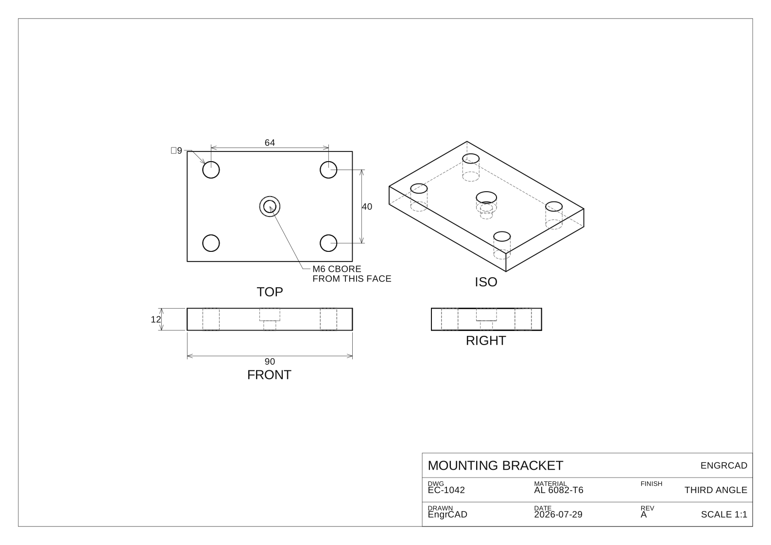
Hidden detail comes out dashed automatically — the four bolt holes and the counterbore are dashed in the front and right views because the probe found material in front of them, not because anyone said so.
Section views
A section view is an ordinary view with a depth: SectionThrough removes
everything nearer the viewer than that point, and the faces the cut lays open are drawn
and hatched.
The cutting plane is perpendicular to the view direction by construction, which is not a limitation but the definition — that is what makes the exposed faces project in true shape, and therefore worth hatching and dimensioning. (For an oblique cut, take a view along the oblique normal.)
var top = SketchPlane.At((0, 0, 9), Vector3d.UnitX, Vector3d.UnitY);var housing = Shape.Cylinder(30, 18).Translate(0, 0, 9)    .Drill(HoleSpec.Counterbore(8, 15, 6), [new Vector2d(0, 0)], depth: 20, top);
var part = new Part("housing", housing);var sheet = new DrawingSheet(SheetFormat.A4);
var plan = new DrawingView(part, StandardViews.DirectionFor("top")!.Value, "TOP"){    Scale = 1,    Center = (90, 140),};plan.Annotate(SheetRadialDimension.Diameter((0, 0), 30, 130));plan.Annotate(SheetRadialDimension.Diameter((0, 0), 7.5, 310));
var section = new DrawingView(part, StandardViews.DirectionFor("front")!.Value, "SECTION A-A"){    Scale = 1,    Center = (215, 140),    SectionThrough = (0, 0, 0),   // cut on the axis, keep the far half};section.Annotate(new SheetLinearDimension((30, 0), (30, 18), -14));section.Annotate(SheetLinearDimension.Horizontal((-30, 0), (30, 0), -16));
sheet.Add(plan).Add(section);sheet.Title = sheet.Title with { Title = "BEARING HOUSING", DrawingNumber = "EC-1043" };
var svg = sheet.ToSvg();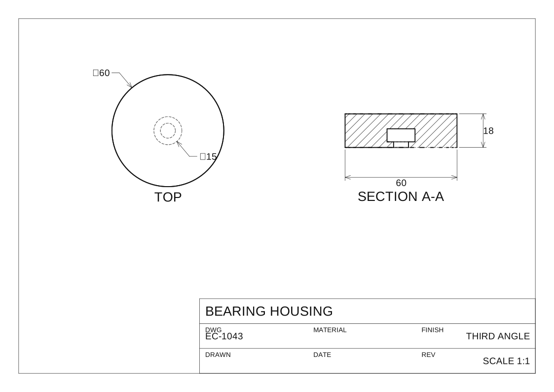
The hatch is clipped exactly to the cut regions by an even-odd scan, so it stops at the bore rather than crossing it, and every cut face on a sheet shares one continuous 45-degree pattern (hatch lines are anchored to the origin, not to each region’s own bounds).
Section, detail and broken views
A drawing is rarely three views of the whole part. A section shows what is inside, a detail blows up a corner too small to dimension, and a broken view elides the dull middle of something long. All three are derived from a view that already exists, and each leaves a mark on the view it came from.
DrawingView.SectionOf builds a section AND the reference that puts the cutting line on
its parent: the chain-dashed line where the plane cuts, an arrow at each end pointing the way
the section looks, and the section’s letter beyond each arrow. The plane shows as a line
exactly when the section’s direction is square to the parent’s — projecting a plane along a
direction that is not in it covers the whole sheet — so anything else is refused by name.
DrawingView.DetailOf blows up a disc of its parent’s projection. It shares the parent’s
projection rather than re-projecting, so it is a clip of exactly the line work the parent
shows, and the parent gets the circle with the detail’s letter beside it.
var top = SketchPlane.At((0, 0, 12), Vector3d.UnitX, Vector3d.UnitY);var housing = Shape.Box(120, 80, 12)    .Drill(StandardHoles.Counterbored(6), LocationSet.Grid(2, 2, 80, 50), depth: 14, top)    .Drill(HoleSpec.Simple(20), [new Vector2d(0, 0)], depth: 14, top);
var part = new Part("housing", housing);var sheet = new DrawingSheet(SheetFormat.A3);
var plan = new DrawingView(part, StandardViews.DirectionFor("top")!.Value, "TOP"){    Scale = 1,    Center = (150, 175),};
// A section of the plan, cut on its own centre line. The cutting line, its arrows and its// letters appear on the PLAN — the sheet reads the reference and draws the mark.var section = DrawingView.SectionOf(    plan, StandardViews.DirectionFor("front")!.Value, new Vector3d(0, 0, 0), "A");section.Center = (150, 70);
// A detail of one bolt hole, at twice the plan's scale.var detail = DrawingView.DetailOf(plan, new Vector2d(-40, 25), 14, magnification: 2, "B");detail.Center = (330, 175);detail.Annotate(SheetRadialDimension.Diameter((-40, 25), 5.5, 40));
sheet.Add(plan).Add(section).Add(detail);sheet.Title = sheet.Title with{    Title = "HOUSING", DrawingNumber = "EC-1120", Material = "AL 6082-T6", Company = "ENGRCAD",};
var svg = sheet.ToSvg();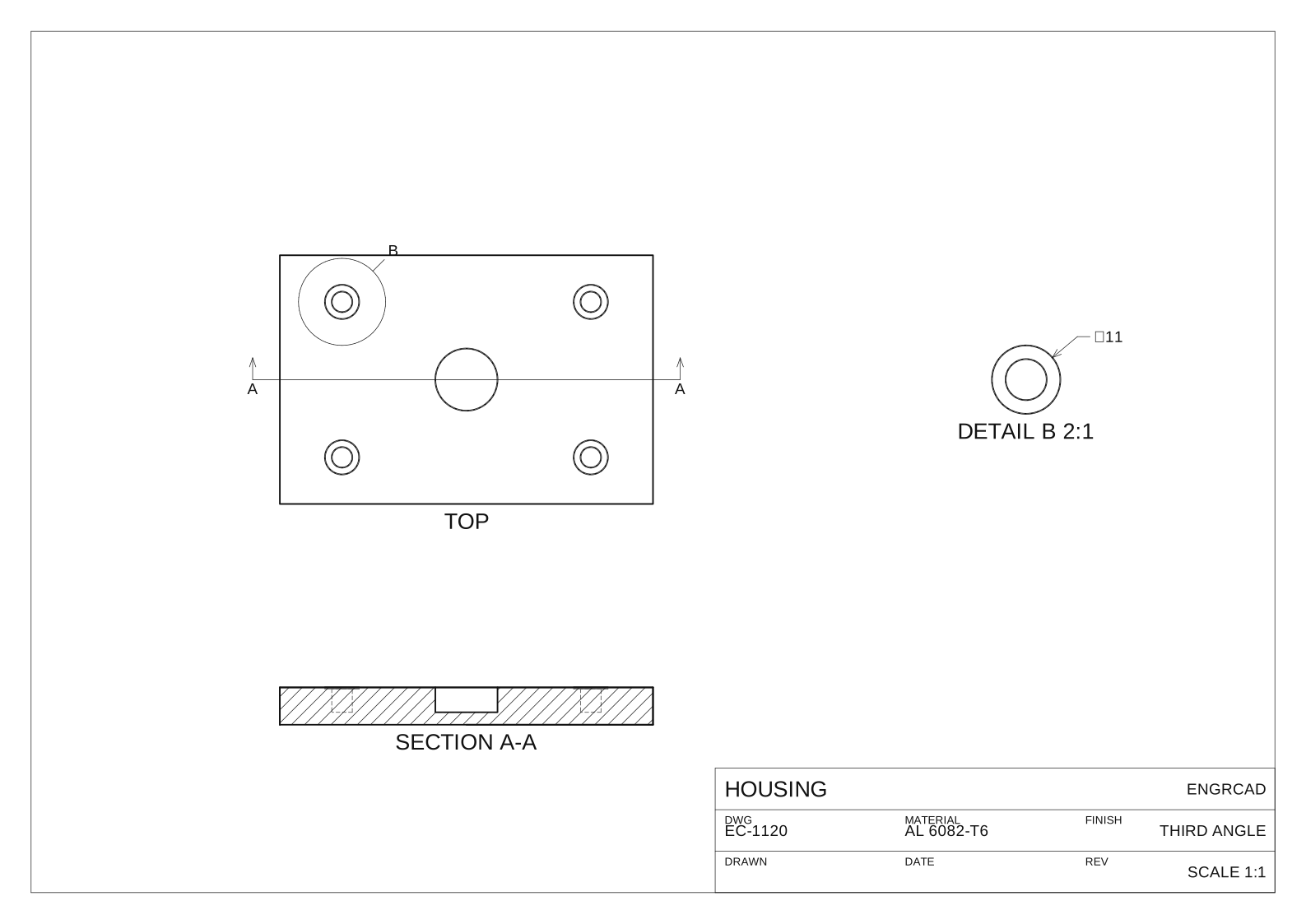
A broken view removes a band of the view’s own coordinates and slides the far side in, so a long part fits the paper at a scale that shows its detail. The break lines mark where the material was elided.
Its dimensions stay true, and that is the whole substance of the feature. A
SheetAnnotation reads its VALUE from its anchors in the view’s model coordinates and draws
its anatomy through the view’s map onto the sheet — so a dimension spanning the break measures
the shaft’s real length while its arrows land on the drawn, shortened view. Nothing has to
remember to state the true value: the value never went through the break at all.
var shaft = new Part("shaft", Shape.Cylinder(12, 400).Rotate(Vector3d.UnitY, Math.PI / 2));
var sheet = new DrawingSheet(SheetFormat.A4);var view = new DrawingView(shaft, StandardViews.DirectionFor("front")!.Value, "SHAFT"){    Scale = 0.5,    Center = (150, 120),    // Elide 260 mm of the middle, leaving 12 mm of drawn gap between the break lines.    Break = ViewBreak.Between(BreakAxis.Horizontal, -130, 130, gap: 12),};
// The overall length is dimensioned across the break and reads 400 -- the part's own length,// not the 152 the drawing spans.view.Annotate(SheetLinearDimension.Horizontal((-200, -12), (200, -12), -16));view.Annotate(SheetLinearDimension.Vertical((-200, -12), (-200, 12), 14));
sheet.Add(view);sheet.Title = sheet.Title with { Title = "DRIVE SHAFT", DrawingNumber = "EC-1121" };
var svg = sheet.ToSvg();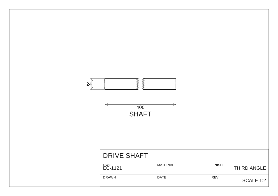
The gap is stated in MODEL units rather than paper millimetres, deliberately: a paper gap would make the view’s size a function of the drawing scale and the scale a function of the view’s size, which is circular.
Auto-dimensioning
AutoDimension.Apply places the dimensions a drawing obviously needs — the overall extents of
each view, and one callout per hole family with its diameter, depth and pattern. It reads the
construction graph, exactly as HoleTable does, rather than measuring
circles in the projection: the drill’s spec, its depth and its points are already in the model,
which is the same reason a hole table cannot put an M6 callout on an M10 hole.
Only the PATTERN is inferred, and that inference is closed form: a bolt circle is “every point
the same distance from their centroid”, which is what LocationSet.Polar constructs, so its
diameter comes back as exactly twice that distance. Anything the recogniser does not know is
reported as no pattern rather than as an approximate one.
Explicit placement stays the contract. Everything the pass adds is an ordinary
SheetAnnotation on the view, so you keep, move or delete any of it. The placement rule is
stated rather than searched — overall width below, overall height left, callouts out to a
common column on the right — which is what makes “nothing it places overlaps anything else or
the view” a property a test can assert rather than a hope.
var top = SketchPlane.At((0, 0, 10), Vector3d.UnitX, Vector3d.UnitY);var flange = Shape.Box(140, 90, 10)    .Drill(StandardHoles.Clearance(8), LocationSet.Polar(6, 45), depth: 12, top)    .Drill(HoleSpec.Simple(30), [new Vector2d(0, 0)], depth: 12, top);
var sheet = new DrawingSheet(SheetFormat.A3);var plan = new DrawingView(new Part("flange", flange), StandardViews.DirectionFor("top")!.Value, "TOP"){    Scale = 1,    Center = (170, 165),};
// One call. The extents come from the view, the callouts from the drill nodes.var placed = AutoDimension.Apply(plan);if (placed.Count < 4)    throw new Exception($"expected extents plus two hole callouts, got {placed.Count}");
sheet.Add(plan);sheet.Title = sheet.Title with{    Title = "PUMP FLANGE", DrawingNumber = "EC-1122", Material = "SS 316", Company = "ENGRCAD",};
var svg = sheet.ToSvg();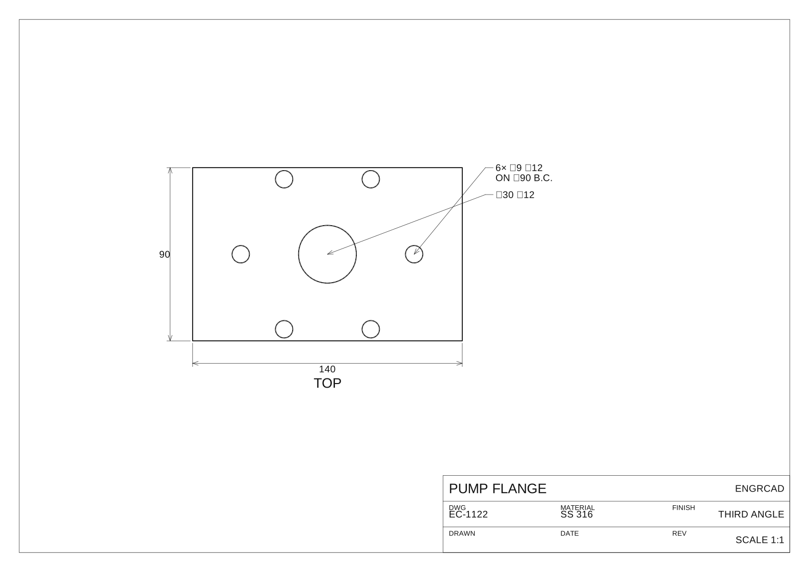
Balloons and a parts list
SheetPartsList draws the parts list above the title block, and BomBalloons.Attach puts a
circled item number on each part in a view. Both read one Bom, so a drawing cannot label
a part with a number its own list does not carry — the item number is the BOM’s own line index,
and there is no second place for it to come from.
The leader anchor is a visible point of the line work of the occurrence it labels. A
projection knows which instance produced each run (HiddenLineRun.Instance), so the balloon
points at the part it names rather than at whatever is nearest, and never at a dashed edge —
which would be pointing through the material at something the reader cannot see. A part with no
visible line work in that view simply gets no balloon.
var baseplate = new Part("BASE PLATE", Shape.Box(140, 90, 12)) { Material = Materials.Steel };var post = new Part("POST", Shape.Cylinder(14, 70).Translate(-40, 0, 12)){    Material = Materials.Aluminium6061,};var cap = new Part("CAP", Shape.Box(50, 50, 10).Translate(40, 0, 12)){    Material = Materials.Aluminium6061,};
var scene = new Scene();scene.Add(baseplate);scene.Add(post);scene.Add(cap);
var sheet = new DrawingSheet(SheetFormat.A3);var iso = new DrawingView(scene, StandardViews.DirectionFor("iso")!.Value, "ASSEMBLY"){    Scale = 1,    Center = (170, 190),};
// One bill of materials feeds both the balloons and the table.var list = new SheetPartsList(Bom.For(scene));var balloons = BomBalloons.Attach(iso, list);if (balloons.Count != 3)    throw new Exception($"expected a balloon per part, got {balloons.Count}");
sheet.PartsList = list;sheet.Add(iso);sheet.Title = sheet.Title with{    Title = "POST ASSEMBLY", DrawingNumber = "EC-1123", Company = "ENGRCAD",};
var svg = sheet.ToSvg();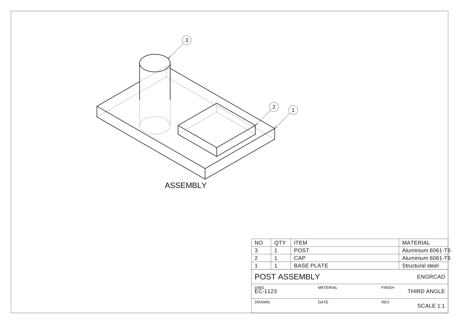
Exporting a sheet
All three writers — SVG, DXF and PDF — consume the same DrawingSheet.Compute()
result, so they cannot disagree about what a drawing looks like — they differ only in
how a polyline, a dash pattern and a piece of text are spelled.
| Class | Layer | SVG | DXF |
|---|---|---|---|
| Visible edge | visible | solid, wide | CONTINUOUS |
| Hidden edge | hidden | dashed, narrow | HIDDEN |
| Cut boundary | section | solid | CENTER |
| Hatch | hatch | narrow solid | CONTINUOUS |
| Dimensions | dimensions | narrow solid | CONTINUOUS |
| Detail circles, break lines | symbol | narrow solid | CONTINUOUS |
| Cutting line | section | chain-dashed | CENTER |
| Border, title block, projection symbol | border, titleblock | narrow solid | CONTINUOUS |
A DXF that names a line type must also define it, or every reader falls back to
solid lines and the classification is lost in transit — so the writer emits an LTYPE
table for every pattern its layers use. A multi-line note travels as one MTEXT
(with the format’s \P breaks and its attachment point), so a DXF consumer sees one
note rather than N unrelated strings — while the SVG and PDF outputs keep drawing the
same stacked lines, the grouping being semantic rather than a second geometry. This round-trips the whole sheet through the
landed reader on every docs build:
var plate = new Part("plate", Shape.Box(60, 40, 12)    .Drill(HoleSpec.Simple(10), [new Vector2d(0, 0)], depth: 14,        SketchPlane.At((0, 0, 6), Vector3d.UnitX, Vector3d.UnitY)));
var sheet = DrawingSheet.StandardLayout(plate, SheetFormat.A4);sheet.Title = sheet.Title with { Title = "PLATE", DrawingNumber = "EC-0001" };sheet.SaveDxf(Path.Combine(Scratch, "plate-drawing.dxf"));
var loaded = DxfDocument.LoadFile(Path.Combine(Scratch, "plate-drawing.dxf"));if (loaded.Diagnostics.Count != 0)    throw new Exception(string.Join("; ", loaded.Diagnostics));if (!loaded.Layers.Contains(SheetLayers.Hidden))    throw new Exception("hidden detail lost its layer");
var titles = loaded.Entities.OfType<DxfText>().Select(t => t.Value).ToList();if (!titles.Contains("PLATE") || !titles.Contains("EC-0001"))    throw new Exception("the title block did not survive the round trip");
PDF — the deliverable format
What actually gets sent to a manufacturer is usually a PDF, so the sheet has a third
writer over the same Compute() result: sheet.ToPdf() / sheet.SavePdf(path).
It is hand-written and dependency-free like every format here, and three choices are
worth knowing:
- The file is uncompressed ASCII with no timestamp and no /ID, so writing the same sheet twice produces byte-identical files — you can diff a drawing revision the way you diff its model. (Both fields are optional per the PDF spec; their natural values are exactly what would break that property.)
- There is no y-flip. PDF’s page origin is the bottom-left with y up — the sheet’s own convention — so the one transform in the file is the millimetre-to-point scale, and every coordinate in the content stream is the sheet’s own millimetre value.
- Text is the built-in Helvetica (the same non-embedded system-font choice the SVG writer makes), encoded as WinAnsi. The drafting diameter sign U+2300, which WinAnsi lacks, is carried as Ø — the standard typographic stand-in; any other character with no WinAnsi form is refused by name rather than silently replaced.
Line classes keep their SVG pens — hidden detail is dashed with exactly the SVG dash pattern, from the same table, so the two exports cannot disagree. This fence verifies the round-trip properties on every docs build:
var plate = new Part("plate", Shape.Box(60, 40, 12)    .Drill(HoleSpec.Simple(10), [new Vector2d(0, 0)], depth: 14,        SketchPlane.At((0, 0, 6), Vector3d.UnitX, Vector3d.UnitY)));
var sheet = DrawingSheet.StandardLayout(plate, SheetFormat.A4);sheet.Title = sheet.Title with { Title = "PLATE", DrawingNumber = "EC-0001" };var path = Path.Combine(Scratch, "plate-drawing.pdf");sheet.SavePdf(path);
// Writing the same sheet twice is a byte fixed point — no timestamps, no random IDs.byte[] first = File.ReadAllBytes(path);if (!first.SequenceEqual(sheet.ToPdf()))    throw new Exception("the PDF is not a deterministic function of the sheet");
// The file is uncompressed ASCII, so its properties are visible to a plain read:// header and trailer, the hidden line class's dash pattern, and the title text.string text = System.Text.Encoding.ASCII.GetString(first);if (!text.StartsWith("%PDF-1.4") || !text.TrimEnd().EndsWith("%%EOF"))    throw new Exception("not a well-formed PDF envelope");if (!text.Contains("[1.2 0.8] 0 d"))    throw new Exception("hidden detail lost its dash pattern");if (!text.Contains("(PLATE)"))    throw new Exception("the title block did not reach the PDF");
(A PDF cannot render as a docs image the way an SVG can, so this fence verifies the file rather than showing it; the figures below show the SHEET each PDF carries, and the tests go further, re-reading every file through an independently written PDF parser and asserting the coordinates round-trip bit for bit.)
sheet.SaveSvg(path), sheet.SaveDxf(path) and sheet.SavePdf(path) write files;
sheet.ToSvg(), sheet.ToDxf() and sheet.ToPdf() hand back the document if you
would rather post-process it.
What a PDF can carry beyond its line work
Four things the writer will do on request. Every one of them is opt-in, and asking for none writes exactly the file above, byte for byte — that property is asserted by a byte comparison rather than argued, which is what makes each of them safe to reach for on a drawing you have already issued.
var pdf = sheet.ToPdf(new PdfSheetOptions{ Layers = true, // toggleable layers in the reader Compress = true, // Flate, ~5x smaller Font = PdfFont.Embed(font), // the drafting symbols, non-Latin text});| plate, A4 | bracket, A3 | |
|---|---|---|
| plain | 21 560 B | 111 652 B |
Layers | 22 272 B | 112 820 B |
Compress | 4 490 B (20.8%) | 21 133 B (18.9%) |
| both | 4 987 B | 21 785 B |
Font embedded (Segoe UI Symbol) | 29 018 B | — |
Font + Compress | 9 631 B | — |
(win-x64, on this page’s own two fixtures — the plate from the SavePdf example above
and the annotated A3 bracket from the top of the page — so the figures are ones you can
rebuild. The embedded row is the whole cost of a subset: the source font is a 2.5 MB,
9 410-glyph file and the drawing’s own characters add 7 458 bytes to the sheet.)
An embedded font — the symbols WinAnsi cannot spell
The built-in Helvetica is encoded as WinAnsi, which has no form for the drafting depth
(↧), counterbore (⌴) or countersink (⌵) signs — a hole callout carrying one is refused
by name rather than silently mangled — and the diameter sign ⌀ only survives as its
O-stroke stand-in Ø. PdfFont.Embed(font) carries a real TrueType font as a subset
of the glyphs the drawing actually uses, addressed by glyph index, so the encoding has
no repertoire to be outside of and the symbols simply travel:
string fonts = Environment.GetFolderPath(Environment.SpecialFolder.Fonts);var font = TrueTypeFont.Load(Path.Combine(fonts, "seguisym.ttf"));
var top = SketchPlane.At((0, 0, 9), Vector3d.UnitX, Vector3d.UnitY);var housing = Shape.Cylinder(30, 18).Translate(0, 0, 9)    .Drill(HoleSpec.Counterbore(8, 15, 6), [new Vector2d(0, 0)], depth: 20, top);
var sheet = new DrawingSheet(SheetFormat.A4);var section = new DrawingView(new Part("housing", housing),                              StandardViews.DirectionFor("front")!.Value, "SECTION A-A"){    Scale = 1,    Center = (150, 120),    SectionThrough = (0, 0, 0),};
// The callout a hole table prints. Three of these characters have NO WinAnsi form, so// the built-in Helvetica cannot draw them as glyphs at all.section.Annotate(new SheetNote((0, 18), (34, 26), "\u23008 \u21A712\n\u2334\u230015 \u21A76"));section.Annotate(SheetLinearDimension.Horizontal((-30, 0), (30, 0), -18));sheet.Add(section);sheet.Title = sheet.Title with { Title = "BEARING HOUSING", DrawingNumber = "EC-1044" };
// Under the built-in Helvetica they become the WORD forms ASME Y14.5 permits, so the// sheet still writes and still reads. That is a substitution rather than a silent drop:// the mapping is public (PdfDrawing.DraftingWords) and the words are the standard's own.string plain = System.Text.Encoding.Latin1.GetString(sheet.ToPdf());if (!plain.Contains("DEEP") || !plain.Contains("CBORE"))    throw new Exception("the drafting symbols should have been spelled out");
// With the font embedded the same sheet carries the SYMBOLS instead - the word forms are// the fallback for a font that cannot spell them, never a downgrade of one that can.var bytes = sheet.ToPdf(new PdfSheetOptions { Font = PdfFont.Embed(font) });if (!System.Text.Encoding.Latin1.GetString(bytes).Contains("/FontFile2"))    throw new Exception("the subset font program did not reach the file");
var svg = sheet.ToSvg();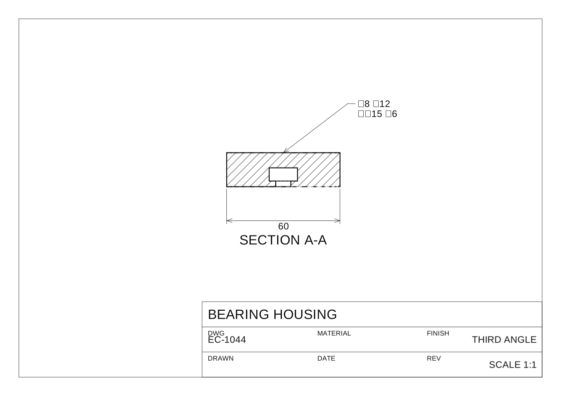
The subset is a deterministic function of the glyph set — the same drawing writes
the same bytes, because the font’s own created/modified date stamps are zeroed on
the way in (they are the /Info problem wearing a font’s clothes) and the glyphs are
visited in index order. It keeps the original glyph NUMBERING rather than renumbering,
which is what lets a composite glyph carry its components across untouched; the cost is
stated rather than hidden, in that the tables are sized by the largest glyph index used
rather than by the count. A PostScript (.otf) font is refused by name.
Toggleable layers
Layers = true puts each line class in a PDF optional-content group, named with the
same SheetLayers names the SVG groups and the DXF layer table use — so hidden detail,
hatch, dimensions and the title block can be switched off in a reader exactly as they
can in a drafting package. It costs a few hundred bytes and moves the declared version
to PDF 1.5 (optional content is a 1.5 feature).
var plate = new Part("plate", Shape.Box(60, 40, 12)    .Drill(HoleSpec.Simple(10), [new Vector2d(0, 0)], depth: 14,        SketchPlane.At((0, 0, 6), Vector3d.UnitX, Vector3d.UnitY)));var sheet = DrawingSheet.StandardLayout(plate, SheetFormat.A4);
// Asking for nothing writes the file it always wrote, byte for byte.if (!sheet.ToPdf().SequenceEqual(sheet.ToPdf(PdfSheetOptions.Default)))    throw new Exception("an all-default options value must be the incumbent file");
byte[] layered = sheet.ToPdf(new PdfSheetOptions { Layers = true });string text = System.Text.Encoding.Latin1.GetString(layered);if (!text.StartsWith("%PDF-1.5"))    throw new Exception("optional content needs PDF 1.5");foreach (string layer in new[] { SheetLayers.Visible, SheetLayers.Hidden, SheetLayers.TitleBlock }){    if (!text.Contains($"/Type /OCG /Name ({layer})"))        throw new Exception($"the {layer} layer did not reach the PDF");}// Marked content must nest: one EMC for every BDC.int opened = System.Text.RegularExpressions.Regex.Matches(text, @"/OC /OC\d+ BDC").Count;int closed = System.Text.RegularExpressions.Regex.Matches(text, @"\bEMC\b").Count;if (opened == 0 || opened != closed)    throw new Exception($"unbalanced marked content: {opened} BDC against {closed} EMC");
Flate compression
Compress = true deflates the content stream (and any embedded font program) — about a
fivefold reduction on a real sheet. It is off by default because an uncompressed
ASCII drawing is what makes a revision diffable and what every assertion here reads
directly; turn it on for a very large sheet. The byte fixed point survives, and the
stronger claim the tests make is that inflating recovers the uncompressed writer’s own
stream byte for byte — compression is a re-spelling and nothing else.
A loose profile, with the approximation named
PDF paths are lines and cubic Béziers, so PdfDrawing.Add(sketch, ...) writes a
sketch’s straight segments and its Béziers EXACTLY (a quadratic having already elevated
to a cubic losslessly on the way into the sketch) while a circular or elliptical arc —
which has no exact PDF form at all — is approximated in the mode you name, to within the
tolerance you state. The returned PdfSketchReport says which segments were which and
measures the deviation from the construction, so nothing has to be guessed at:
// Lines and arcs, plus one cubic: a bracket outline with a bore.var profile = Sketch.Start(0, 0)    .LineTo(40, 0)    .ArcTo((52, 12), radius: 12, clockwise: false)    .LineTo(52, 30)    .BezierTo((40, 42), (14, 42), (0, 30))    .Close()    .WithHole(Sketch.Circle(new Vector2d(26, 18), 7));
// Cubic Béziers ride into the file verbatim; the arcs do not, so they are approximated// by the standard k = (4/3)tan(theta/4) construction to a stated 0.01 mm.var pdf = new PdfDrawing { Margin = 6 };var report = pdf.Add(profile, PdfCurveMode.Kappa, tolerance: 0.01);if (report.ApproximatedSegments == 0 || report.MaxDeviation > 0.01)    throw new Exception($"expected arcs approximated within the tolerance, got {report}");pdf.SaveFile(Path.Combine(Scratch, "bracket-profile.pdf"));
// The other mode flattens the arcs to polylines. It honours the same tolerance and is// strictly worse on both counts, which is the durable claim rather than the byte totals// quoted below: cubics are smaller AND land closer to the arc they stand in for.var flat = new PdfDrawing { Margin = 6 };var flatReport = flat.Add(profile, PdfCurveMode.Flatten, tolerance: 0.01);if (flat.ToPdf().Length <= pdf.ToPdf().Length)    throw new Exception("the cubic route should be the smaller file");if (flatReport.MaxDeviation <= report.MaxDeviation)    throw new Exception("the cubic route should be the closer approximation");if (flatReport.ExactSegments != report.ExactSegments)    throw new Exception("the lines and the cubic are exact in either mode");
// The same profile as SVG, which CAN carry an arc exactly - so this picture is the// geometry the PDF approximates, not the approximation.var drawing = new SvgDrawing { Margin = 6 };drawing.Add(profile);var svg = drawing.ToSvg();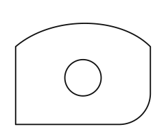
PdfCurveMode.Flatten writes polylines instead; both honour the same stated deviation,
and the cubic route reaches it far more cheaply — measured on the bracket profile above
at its stated 0.01 mm tolerance, 1 084 bytes against 3 853, at a measured deviation
of 3.3e-3 against 9.9e-3. The error of the cubic construction has an exact closed form,
PdfDrawing.ArcCubicDeviation, which is worth knowing for two reasons: the cubic lies
strictly OUTSIDE the arc (it never cuts into the part), and the error falls as the
sixth power of the span, so halving the number of spans multiplies it by 64 rather
than by the 16 a fourth-order rule would give. A quarter turn reads 2.7253e-4 of the
radius.
The shared frame
The paper, the border and the title block are a DrawingFrame — one value type both this
mechanical sheet and the ECAD schematic sheet draw from, so a
drawing and a schematic of one project share one look and cannot drift. It is one pure
function of its parameters (sheet.Frame().Compute()), which is the whole point: two sheets
given the same paper, the same title-block fields and the same frame options produce
byte-identical furniture because they call one function. The two blocks differ today — the
mechanical block is a three-band engineering layout, the schematic block a two-band one — so
the frame carries both parameterisations and each sheet picks its own; the extraction unified
the code and the value type, not the default appearance.
SheetFormat is the one paper-size table the frame reads: the ISO 216 A and B series
and the ANSI/ASME Y14.1 A–E sizes (SheetFormat.All), all landscape, .Portrait to turn
one over.
Opt-in sheet standards (ISO 5457)
FrameStandards adds standard furniture, off by default so an existing sheet is
byte-identical. FrameStandards.Iso5457 draws the ISO 5457 border: a zone grid (column
numbers across, row letters down each side, with I and O omitted) and centring marks at
the middle of each side — all in the margin band, so they never reach the drawing area.
var scene = new Scene();scene.Add(new Part("plate", Shape.Box(80, 50, 10)    .Drill(HoleSpec.Simple(8), [new Vector2d(0, 0)], depth: 12,        SketchPlane.At((0, 0, 5), Vector3d.UnitX, Vector3d.UnitY))));
var sheet = DrawingSheet.StandardLayout(scene, SheetFormat.A3);sheet.Title = sheet.Title with{    Title = "SPACER PLATE", DrawingNumber = "EC-2001", Company = "ENGRCAD",};
// Opt in to the ISO 5457 border: a zone grid and centring marks, drawn in the margin band.sheet.Standards = FrameStandards.Iso5457;
var svg = sheet.ToSvg();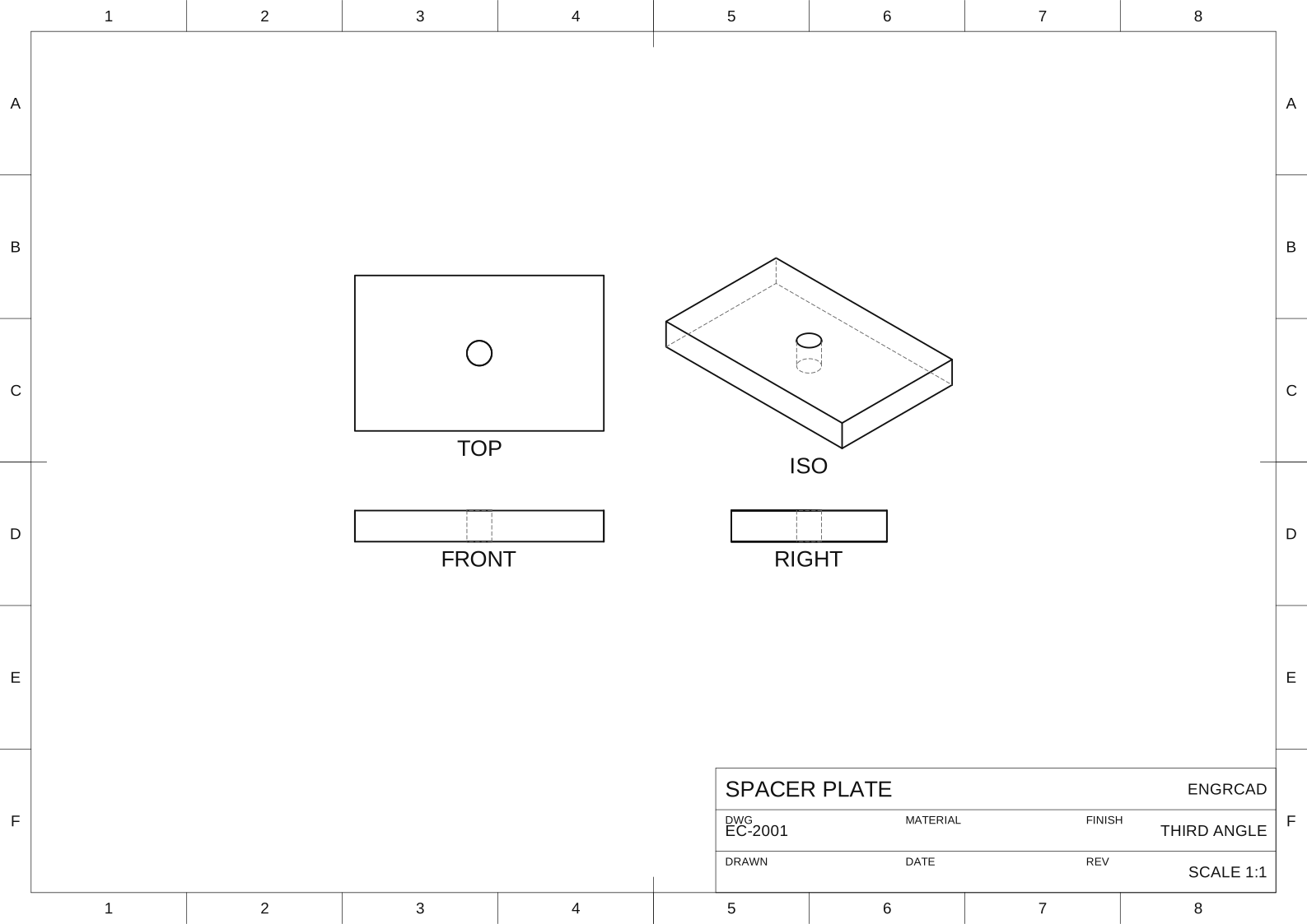
The zone COUNTS are ISO 5457’s own, transcribed per sheet size
(Iso5457Zones) — A0 is 24 fields along its long side by 16 across, down to A4’s 6 by 4 — and a
paper the standard does not tabulate falls back to rounding the border to a nominal field size
(FrameStandards.NominalZone), which is not a lesser answer for a custom sheet: 25–75 mm is
what the standard says a field should be. The match is on the paper’s own dimensions rather
than a format name, so a .Portrait sheet and a custom format that happens to measure A3 both
get A3’s counts — the counts are a property of the paper, and a name is not.
A table replacing a rounding is a change to existing output, so it is worth saying which sheets move: A0, A1 and A2 each gain one division where the rounding fell short (A0 23 → 24 columns, A1 11 → 12 rows, A2 11 → 12 columns), while A3 and A4 are unchanged — so every committed A3 or A4 drawing is byte-identical to what it was.
The projection symbol (ISO 128)
FrameStandards.ProjectionSymbol draws the truncated cone in two views beside the title block.
It is derived rather than transcribed: put the frustum’s axis along the sheet’s x with its
small end to the left, and the other view is the one looking along the axis at that small end —
a view from the LEFT. The sheet’s own layout rule places a view from the left on the left in
third angle and on the right in first, so the pair of circles swaps sides while the trapezoid
does not. Reading the symbol off the layout rule rather than off a picture is what stops the
symbol and the layout disagreeing.
It needs both halves to ask for it — the standards must switch it on and the frame must know its angle — so a frame that predates it draws exactly what it always did.
var scene = new Scene();scene.Add(new Part("keeper", Shape.Box(70, 45, 14)    .Drill(StandardHoles.Clearance(5), LocationSet.Grid(2, 2, 46, 26), depth: 16,        SketchPlane.At((0, 0, 7), Vector3d.UnitX, Vector3d.UnitY))));
// First angle: every view lands on the OPPOSITE side from third, and the symbol follows,// because both read the one layout rule.var sheet = DrawingSheet.StandardLayout(scene, SheetFormat.A3, ProjectionAngle.First);sheet.Title = sheet.Title with{    Title = "KEEPER PLATE", DrawingNumber = "EC-2002", Company = "ENGRCAD",};sheet.Standards = FrameStandards.None with { ProjectionSymbol = true };
var svg = sheet.ToSvg();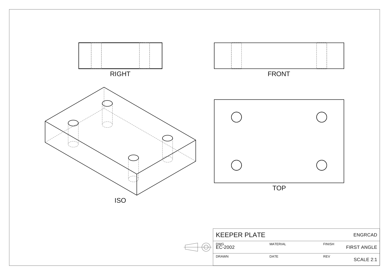
An ISO 7200 title block
Iso7200TitleBlock is a second TitleBlockLayout beside the engineering one, printing
ISO 7200’s data fields: the legal owner, the title
and its supplementary title, the identification number, document type and revision, and who
created and approved it, when, in what language and on which sheet. The four fields the standard
makes mandatory — legal owner, identification number, date of issue and sheet number — are
marked as such in Iso7200TitleBlock.Fields, which is the transcription a test reads back
rather than a list buried in the layout. ⚠ The field list is transcribed; verify it against the
standard before it goes on a controlled drawing.
A field the drawing has not stated prints its caption and nothing else, which is what a blank
form does. The layout is an override (DrawingSheet.TitleBlockLayoutOverride), so a sheet that
says nothing keeps the engineering block.
var scene = new Scene();scene.Add(new Part("bracket", Shape.Box(90, 60, 10)    .Drill(StandardHoles.Clearance(6), LocationSet.Grid(2, 2, 60, 36), depth: 12,        SketchPlane.At((0, 0, 5), Vector3d.UnitX, Vector3d.UnitY))));
var sheet = DrawingSheet.StandardLayout(scene, SheetFormat.A3);sheet.Title = sheet.Title with{    Company = "ENGRCAD LTD",    Title = "MOUNTING BRACKET",    Project = "TEST RIG 4",    DrawingNumber = "EC-1124",    DocumentType = "DRAWING",    Revision = "B",    Author = "EngrCAD",    ApprovedBy = "C. JONES",    Date = "2026-08-17",    Language = "en",    Sheet = "1 / 1",};
// The ISO 7200 field layout, and the ISO 128 projection symbol beside it.sheet.TitleBlockLayoutOverride = Iso7200TitleBlock.Default;sheet.Standards = FrameStandards.Iso5457 with { ProjectionSymbol = true };
var svg = sheet.ToSvg();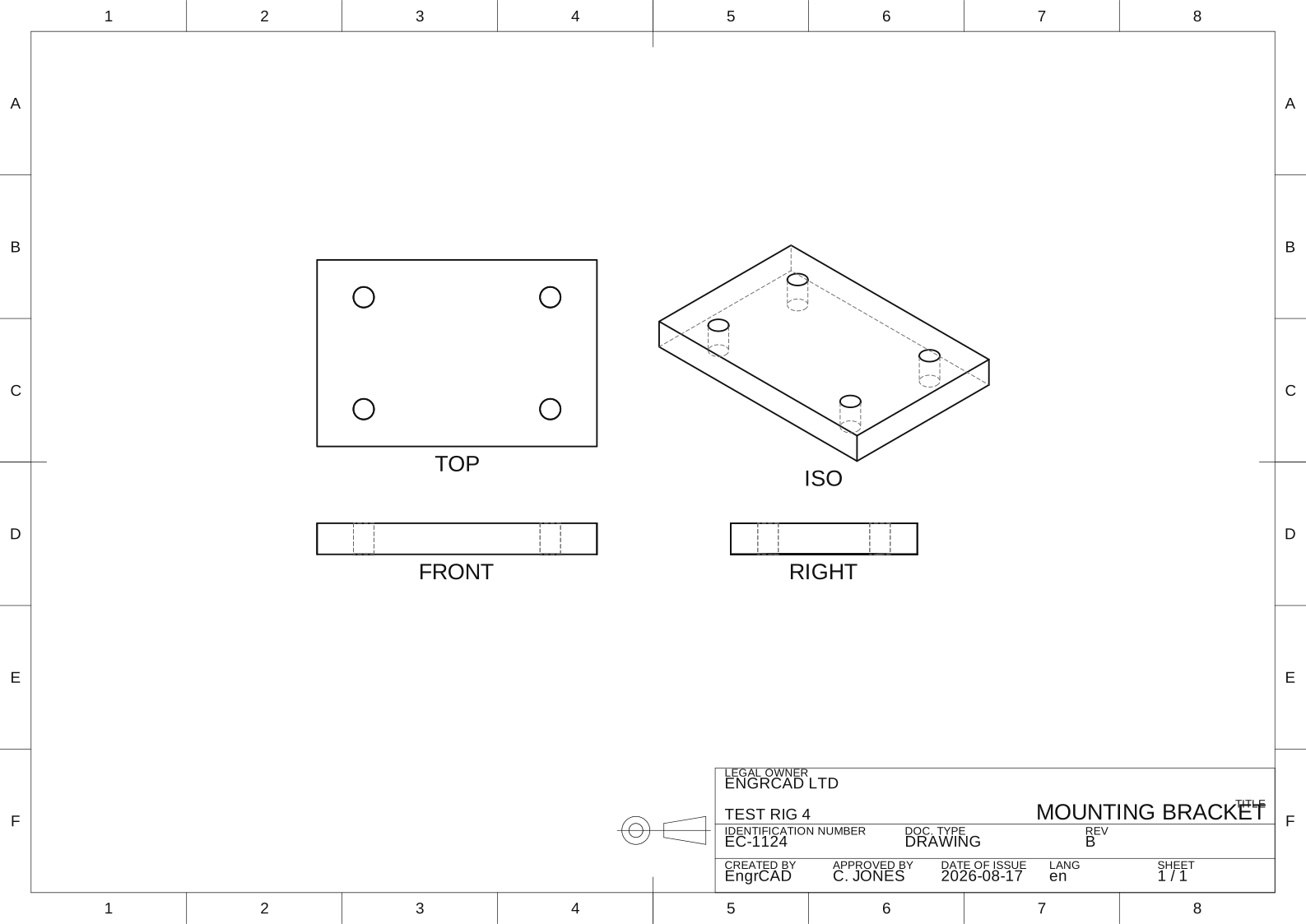
Putting a whole drawing together
Nothing here is a mode, so the pieces compose: a standard layout, a section marked on its own parent, auto-dimensions read off the construction graph, and the ISO 5457 border with its projection symbol — each an ordinary call on the same sheet.
var top = SketchPlane.At((0, 0, 9), Vector3d.UnitX, Vector3d.UnitY);var manifold = Shape.Box(120, 70, 18)    .Drill(StandardHoles.Counterbored(6), LocationSet.Grid(2, 2, 90, 46), depth: 20, top)    .Drill(HoleSpec.Simple(24), [new Vector2d(0, 0)], depth: 20, top);
var part = new Part("manifold", manifold);var sheet = new DrawingSheet(SheetFormat.A3);
var plan = new DrawingView(part, StandardViews.DirectionFor("top")!.Value, "TOP"){    Scale = 1,    Center = (150, 190),};AutoDimension.Apply(plan);
// The section marks its own cutting line, arrows and letters on the plan.var section = DrawingView.SectionOf(    plan, StandardViews.DirectionFor("front")!.Value, new Vector3d(0, 0, 0), "A");section.Center = (150, 80);
sheet.Add(plan).Add(section);sheet.Standards = FrameStandards.Iso5457 with { ProjectionSymbol = true };sheet.Title = sheet.Title with{    Title = "MANIFOLD BODY",    DrawingNumber = "EC-2003",    Material = "AL 6082-T6",    Company = "ENGRCAD",    Project = "TEST RIG 4",    Sheet = "1 / 1",};
var svg = sheet.ToSvg();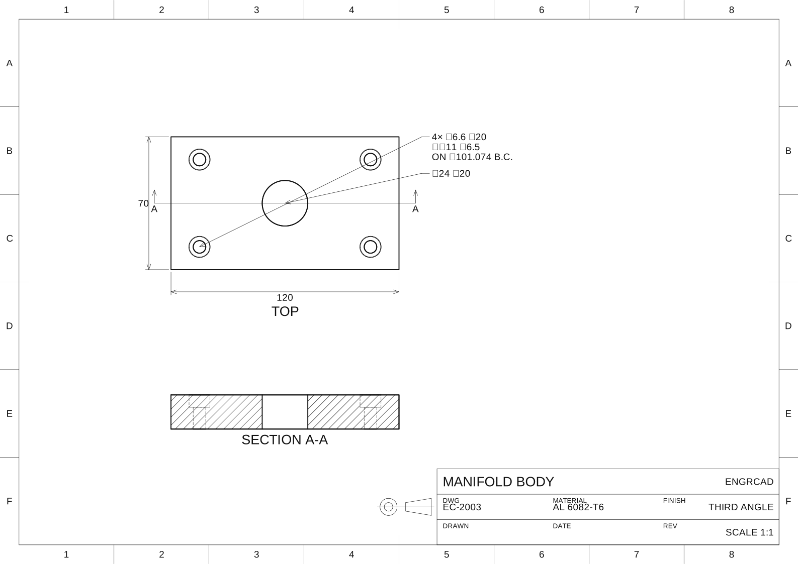
What the projection is honest about
The line work is exact wherever the kernel has it: for a B-Rep-backed part the
edges are sampled from the actual edge curves at display resolution, so a bore rim is a
smooth circle however coarse the mesh. Two things are not exact, and the output says so
via HiddenLineRun.Source:
- The outline of a smooth surface (
EdgeSource.Silhouette). A cylinder seen from the side has no modelled edge along its outline, so one is taken from the display mesh’s view-dependent silhouette. It is faceted at mesh resolution. True silhouette curves on curved surfaces are the known upgrade. - Visibility itself. The question “is there material in front of this point” is
answered against the display mesh, so a coarser mesh means a coarser dash boundary.
It is refined by bisection to
HiddenLineOptions.SplitFraction(1e-5 of the model’s extent by default), which is far finer than a drawn line is wide.
Everything else is decided exactly. The first stage of the visibility test reads the point’s own surface: if every face around it points away from the viewer, it is buried in its own material and is hidden with no ray cast at all — which settles most of a solid’s edges, for free and without touching a mesh.
var part = new Part("box", Shape.Box(40, 20, 10));var iso = StandardViews.SheetFrame(StandardViews.DirectionFor("iso")!.Value);var result = HiddenLineRemoval.Project(part, iso);
// Seen from a corner, exactly the three edges meeting at the FAR corner are hidden;// an axis-parallel edge of length L projects to L*sqrt(2/3) from the iso direction.double expected = (40 + 20 + 10) * Math.Sqrt(2.0 / 3);double hidden = result.Hidden.Sum(r => r.Length);if (Math.Abs(hidden - expected) > 0.2)    throw new Exception($"expected about {expected:F2} of dashed line, got {hidden:F2}");if (result.Runs.Any(r => r.Source == EdgeSource.Silhouette))    throw new Exception("a box has no smooth surface to silhouette");
Options
HiddenLineOptions is scale-free: every length is a fraction of the projected
geometry’s extent, so a drawing of a 4 mm dowel and a drawing of a 4 m beam behave
the same.
| Option | Default | What it does |
|---|---|---|
BiasFraction | 1e-3 | How far a probe steps off the surface before casting. Must exceed the tessellation’s chord error; raise it for a deliberately coarse mesh. |
SampleFraction | 1/200 | Spacing of visibility samples along an edge. |
SplitFraction | 1e-5 | How precisely a dash boundary is located by bisection. |
MinimumRunFraction | 2e-3 | Runs shorter than this are absorbed into their neighbour — the “shorter than a pen stroke” rule. |
IncludeSilhouette | true | Draw the mesh-derived outline of smooth surfaces. |
IncludeHidden | true | Emit hidden runs at all. |
SectionThrough | null | Cut everything nearer the viewer than this point. |
Parts follow the same visibility rules an export does: a Hidden part contributes
nothing (not even occlusion), a Ghost part is left off (a translucent line means
nothing on paper), and a part with ClippedBySection = false passes through a section
whole — the drafting convention that shafts, bolts, nuts, keys and pins are drawn
unsectioned.
Related
- 2D views —
Shape.SectionandShape.Silhouette, the region-level projections a sheet’s cut faces are built from. - DXF & SVG — the 2D interchange layer a sheet writes through.
- 3D annotations (PMI) — the same dimension anatomy attached to the model itself rather than to a sheet.