Frames & weldments
Weldment builds a frame of straight structural members on a skeleton of runs — the
SolidWorks-weldments capability, assembled from machinery that already exists: a
profile is a sketch (so a hollow section’s wall thickness
is exact), each member is one extrusion of it, a joint is an exact bisector-plane cut,
and the cut list is the BOM reading each member’s stock length.
FrameProfile has factories for flat bar, SHS/RHS box sections, equal angles, plain
channels and round tube (plus a small StandardSections catalogue of common metric
sizes — nominal EN-series dimension sets, verify against the current datasheet), and
any custom closed sketch works. The run line passes through the profile sketch’s
origin: symmetric sections are centred on it, an angle sits with its heel on it.
var shs = StandardSections.Shs25x2;
// A table frame: a mitred top rectangle on four legs.var top = Weldment.Path(shs,    [new Vector3d(0, 0, 300), new Vector3d(360, 0, 300),     new Vector3d(360, 240, 300), new Vector3d(0, 240, 300)],    closed: true, new WeldmentOptions { Material = Materials.Steel, Name = "top" });var legs = Weldment.Build(shs,[    (new Vector3d(0, 0, 0), new Vector3d(0, 0, 287.5)),    (new Vector3d(360, 0, 0), new Vector3d(360, 0, 287.5)),    (new Vector3d(360, 240, 0), new Vector3d(360, 240, 287.5)),    (new Vector3d(0, 240, 0), new Vector3d(0, 240, 287.5)),], new WeldmentOptions { Material = Materials.Steel, Name = "legs" });
var scene = new Scene();var tab = scene.AddTab("stand");tab.Add(top.ToAssembly());tab.Add(legs.ToAssembly());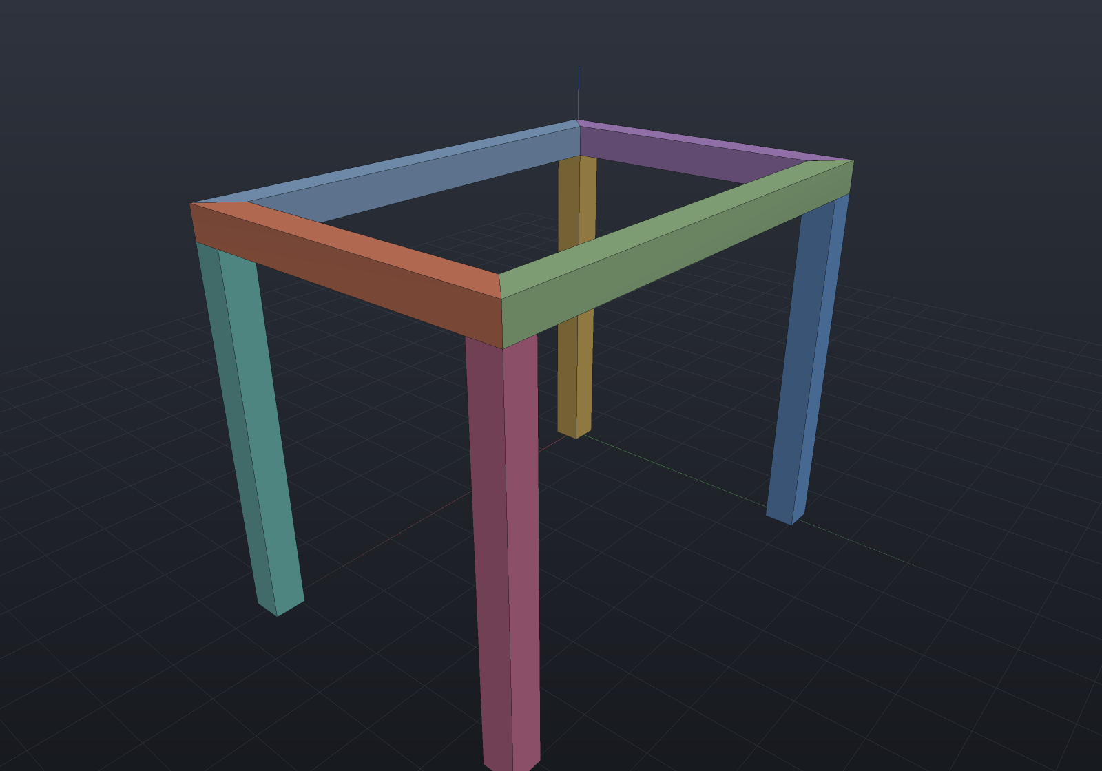
Joints are detected wherever exactly two runs share an endpoint (a Path shares them
by construction). Under the default FrameJointStyle.Miter both members are cut back
by the exact bisector plane — for a joint at j between members leaving along
unit directions a and b, the plane through j with normal a − b, which
contains both the angle bisector and the axes’ common normal with no division
anywhere. Each member is extruded overlong past the joint and a box tool whose base
face lies exactly on that plane subtracts the stub, so every boolean is transversal
(never coplanar input) and every cut curve is analytic: plane∩plane lines on
polygonal sections, the exact plane∩cylinder ellipse on a mitred round tube.
The two halves of a joint are separate parts meeting face-to-face on the
bit-identical plane, which is what makes the volumes verifiable in closed form: a
prism cut by planes at both ends has volume A · (axial distance between the planes' crossings of the centroid fiber) — so a mitred member of a centred profile is
exactly A·L, and a closed rectangular frame totals exactly A · perimeter.
T-joints
A run ending on another run’s interior is a T-joint: the through member keeps its
full section past the joint — the same role the butt joint’s through run plays — and
the abutting member is trimmed back by the through member’s facing wall plane, so the
weld gap is exactly zero and the volumes stay closed forms (the rail below keeps
exactly A · (run length − half the post's width)).
var shs = StandardSections.Shs40x3;var frame = Weldment.Build(shs,[    // The through rail, a mid-post butting its side, and an ordinary corner post.    (new Vector3d(0, 0, 0), new Vector3d(400, 0, 0)),    (new Vector3d(200, 0, 180), new Vector3d(200, 0, 0)),    (new Vector3d(0, 0, 180), new Vector3d(0, 0, 0)),], new WeldmentOptions { Up = Vector3d.UnitY, Material = Materials.Steel });
var scene = new Scene();scene.AddTab("tee").Add(frame.ToAssembly());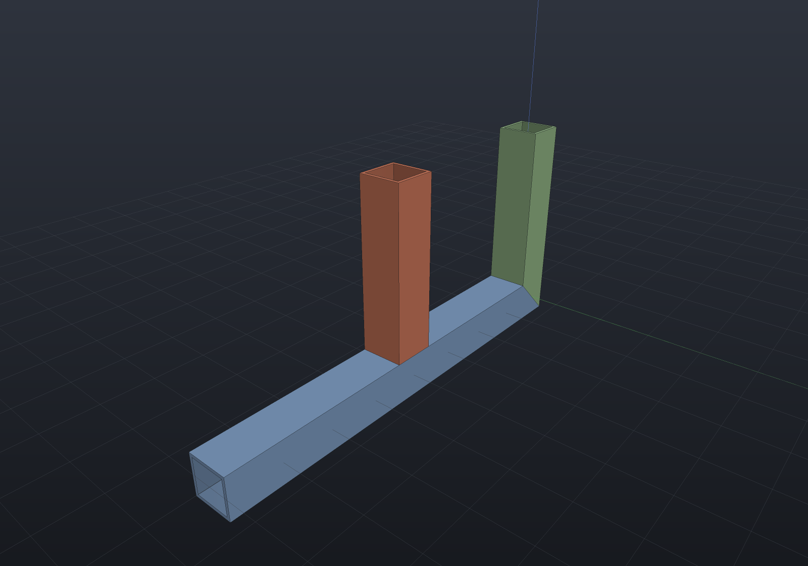
Profiles may be mixed per skeleton — legs SHS, rails flat — by handing Build
(or Path) a per-run override list aligned with the runs (profiles: [null, flat],
null keeping the default). The miter is unchanged (one bisector plane cuts both
members, each keeping its own section; the weld gap a smaller section leaves against
a larger one is the welder’s, not the kernel’s), and a butt or T trim reads the
through member’s own wall offset — a flat rail butting an SHS 40 post is trimmed
back by the post’s half-width, exactly.
What a T-joint refuses is the shapes with no one honest answer, each by name: a collinear landing (the members overlap along one line — split the through run instead), an endpoint on two interiors (which wall trims is ambiguous), a three-member confluence (an end joint whose point also lies on a third run’s interior), and a round-walled through member — that is the coped saddle again, refused with the tracer reason.
The BOM is the cut list
Every member’s Part carries CutLength — its exact overall axial extent after
trimming (a mitred end counts to its longest point), which is the stock you order.
BomLine.CutLength projects it, the BOM’s text and CSV reports gain a CUT column
plus a total-stock footer whenever any line states one, and identical members share
their name (designation x cut length) so Bom.ByItem() rolls them up into one
cut-list line per stock length:
var shs = StandardSections.Shs40x3;var frame = Weldment.Path(shs,    [new Vector3d(0, 0, 0), new Vector3d(500, 0, 0),     new Vector3d(500, 0, 300), new Vector3d(0, 0, 300)],    closed: true,    new WeldmentOptions { Up = Vector3d.UnitY, Material = Materials.Steel });
var bom = Bom.For(frame.ToAssembly());Console.WriteLine(bom.ToText(mass: true));foreach (var (item, quantity, _) in bom.ByItem())    Console.WriteLine($"cut {quantity} x {item}");
Scope, honestly
Straight members, one profile per run (a default plus per-run overrides); joints of
exactly two members. Butt
joints trim the later run back to the earlier (through) member’s flat wall, and a
T-joint trims a run ending mid-member back the same way — while a
round tube as the through member is the coped saddle joint, which is refused by
name rather than approximated: the saddle is a transcendental cylinder∩cylinder
intersection the surface-intersection tracer is known to under-seed at
structural-section scales, so the cut would be a sampled polyline whose error no
tessellation density can lower. Multi-member joints, zero-angle joints, members
consumed by their own end cuts and joint trims of Bézier-outline profiles are all
refused by name; curved members and corner reliefs are future work.