Sketching
2D sketches are the profile language for extrude, revolve, and sweep.
Draw them with the fluent builder — LineTo, ArcTo, ArcThrough, EllipticalArcTo,
BezierTo, QuadraticTo — or start from a primitive, and punch holes with WithHole.
The fluent builder
var plate = Sketch.Start(-20, -12)    .LineTo(20, -12)    .ArcTo(new(20, 12), radius: 14, clockwise: false)   // bulged arc on the right    .LineTo(-20, 12)    .BezierTo(new(-34, 7), new(-34, -7), new(-20, -12)) // sculpted bézier on the left    .Close()    .WithHole(Sketch.Circle(new(11, 0), 4.5))    .WithHole(Sketch.Circle(new(-13, 0), 3));
var scene = new Scene();scene.Add(new Part("sketched plate", Shape.Extrude(plate, 5), Palette.Steel));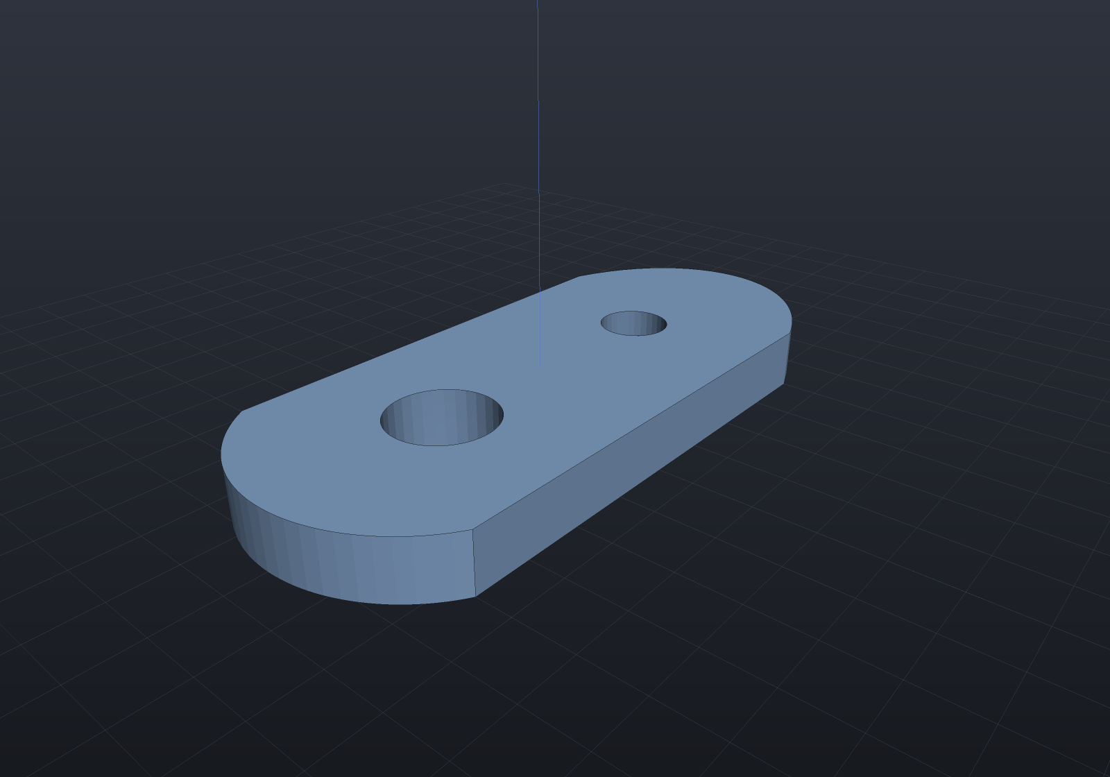
Lines and arcs lower to exact rational NURBS profiles for B-Rep, and every sketch
knows its exact 2D signed distance (sketch.ToRegion()), which makes sketch
extrusions and full revolutions native in the implicit engine too — no mesh bridge.
sketch.Area() is exact (arc terms analytic, béziers by Gauss quadrature).
Sketch primitives
Rectangle, RoundedRectangle, Circle, Polygon, and Slot cover the common
profiles without builder ceremony:
var scene = new Scene();double x = -48;foreach (var (name, sketch) in new (string, Sketch)[]{ ("rectangle", Sketch.Rectangle(18, 12)), ("rounded", Sketch.RoundedRectangle(18, 12, 3)), ("circle", Sketch.Circle(7.5)), ("polygon", Sketch.Polygon([new(-9, -7), new(9, -7), new(0, 9)])), ("slot", Sketch.Slot(length: 18, width: 8)),}){ scene.Add(new Part(name, Shape.Extrude(sketch, 4), Palette.Sky, Matrix4d.CreateTranslation((x, 0, 0)))); x += 24;}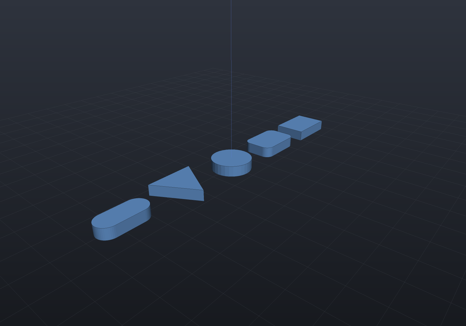
Elliptical arcs
Sketch.Ellipse and the builder’s EllipticalArcTo carry an ellipse exactly — the
segment stores the centre and both semi-axis vectors, so a rotated ellipse needs no
third parameter and there is no flattened polyline anywhere in the chain. That makes an
elliptical profile native in all three representations, exactly like a circular one:
πab from Area(), an exact 2D distance field, and an Ellipse3d in the B-Rep.
EllipticalArcTo is SVG’s A rx ry rotation largeArc sweep command with the same two
flags and the same meaning, including SVG’s out-of-range rule — semi-axes too small to
span the chord are scaled up by the common factor that just reaches, so the ellipse’s
aspect and rotation survive and you never have to solve for the minimum ellipse
before drawing.
// A full ellipse, a rotated one, and a slotted plate whose ends are elliptical arcs.var oval = Sketch.Ellipse(semiX: 11, semiY: 6);var tilted = Sketch.Ellipse(default, semiX: 11, semiY: 6, rotationDegrees: 35);
var plate = Sketch.Start(-9, -6)    .LineTo(9, -6)    .EllipticalArcTo(new(9, 6), semiX: 5, semiY: 6)     // right cap: a half-ellipse    .LineTo(-9, 6)    .EllipticalArcTo(new(-9, -6), semiX: 5, semiY: 6)   // left cap    .Close()    .WithHole(Sketch.Ellipse(default, 6, 2.5, rotationDegrees: -20));
var scene = new Scene();scene.Add(new Part("ellipse", Shape.Extrude(oval, 4), Palette.Steel,    Matrix4d.CreateTranslation((-30, 0, 0))));scene.Add(new Part("rotated", Shape.Extrude(tilted, 4), Palette.Sky));scene.Add(new Part("elliptical ends", Shape.Extrude(plate, 4), Palette.Brass,    Matrix4d.CreateTranslation((32, 0, 0))));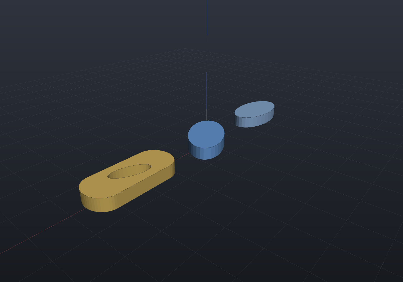
One consequence worth knowing: an ellipse with equal semi-axes is geometrically a
circle but stays an Ellipse2d, so BrepQueries.IsCircular and cylinder promotion will
not claim it. Use Sketch.Circle when the shape really is a circle.
Everything else in the sketch vocabulary works on an elliptical arc: it round-trips
through ToCurves/FromCurves (so it survives feature persistence), exports as an
exact SVG A command, and moves with its chord under the constraint solver. What it
does not yet have is its own constraint variables — like a bézier, only its endpoint
joints can be constrained, and a tangency to an elliptical arc is not in the vocabulary.
Sketch constraints
Draw roughly, constrain, solve exact. sketch.Constrain() opens the variational
constraint layer: coincident, horizontal/vertical, parallel/perpendicular, tangent,
equal, concentric and fix constraints plus distance/angle/radius/diameter dimensions,
solved by Levenberg–Marquardt from the sketch as drawn — the drawing is the seed
and the branch selector (a tangent arc stays on the side it was drawn on). The result
is an ordinary Sketch that extrudes, revolves and sweeps like any other.
Below, a rounded rectangle drawn by hand — nothing square, radii disagreeing — next to the same sketch fully constrained to a 30 × 20 plate with R2 fillets (zero degrees of freedom remain):
// Drawn by hand: nothing is square, the corners are off, the radii disagree.var drawn = Sketch.Start(12.8, -10.3)    .ArcTo(new(15.3, -8.1), 2.3, clockwise: false)    .LineTo(15.1, 7.6)    .ArcTo(new(12.9, 10.2), 1.8, clockwise: false)    .LineTo(-12.7, 10.4)    .ArcTo(new(-15.2, 8.2), 2.1, clockwise: false)    .LineTo(-14.8, -7.7)    .ArcTo(new(-13.1, -9.8), 2.0, clockwise: false)    .Close();
var cs = drawn.Constrain();cs.Vertical(cs.Line(1)).Horizontal(cs.Line(3)).Vertical(cs.Line(5)).Horizontal(cs.Line(7))  .Tangent(cs.Line(7), cs.Arc(0)).Tangent(cs.Line(1), cs.Arc(0))  .Tangent(cs.Line(1), cs.Arc(2)).Tangent(cs.Line(3), cs.Arc(2))  .Tangent(cs.Line(3), cs.Arc(4)).Tangent(cs.Line(5), cs.Arc(4))  .Tangent(cs.Line(5), cs.Arc(6)).Tangent(cs.Line(7), cs.Arc(6))  .EqualRadius(cs.Arc(0), cs.Arc(2))  .EqualRadius(cs.Arc(0), cs.Arc(4))  .EqualRadius(cs.Arc(0), cs.Arc(6))  .Radius(cs.Arc(0), 2)  .Distance(cs.Point(1), cs.Point(2), 16)   // right edge = height − 2r  .Distance(cs.Point(3), cs.Point(4), 26)   // top edge = width − 2r  .Fix(cs.Point(0));
var result = cs.Solve();                    // throws if the constraints contradictvar solved = result.Sketch!;                // IsFullyConstrained: 0 DOF remain
var scene = new Scene();scene.Add(new Part("drawn", Shape.Extrude(drawn, 4), Palette.Steel));scene.Add(new Part("solved", Shape.Extrude(solved, 4), Palette.Sky,    Matrix4d.CreateTranslation((36, 0, 0))));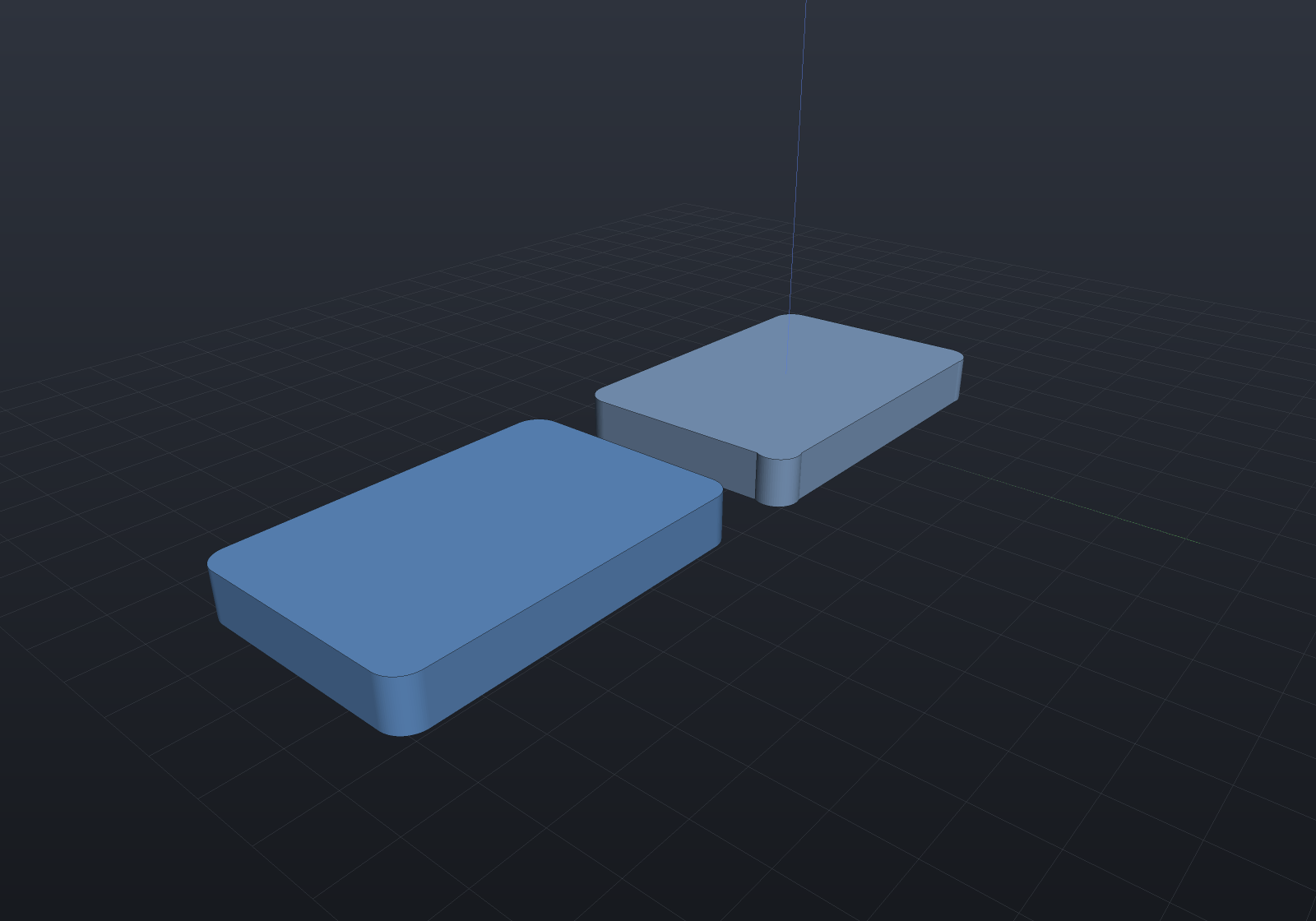
The solve report is honest about freedom: under-constrained is normal (the Levenberg–Marquardt step lies in the Jacobian’s row space, so geometry no constraint mentions keeps its drawn proportions, and the remaining degree-of-freedom count is always reported — rank-revealing, so redundant constraints are not miscounted). A consistent extra dimension converges and reports the redundancy; a contradictory one fails naming the constraints that cannot drop, and a failed solve produces nothing — the drawn sketch is never modified:
FAILED in 6 iterations; worst residual 1; 1 of 8 DOF constrained (7 free); 1 redundant row · 'Distance(outer point 0, outer point 1) = 10' is off by 1 · 'Distance(outer point 0, outer point 1) = 12' is off by 1 · no solved sketch was produced — the drawn sketch is unchangedEntities address the sketch’s normalized segment order, holes included — a washer is
cs.Concentric(cs.Arc(0), cs.HoleArc(0, 0)) plus two diameters. Full circles carry
center + radius only (constrain them via CenterOf); bézier and elliptical-arc segments
carry no shape variables and ride the similarity of their two endpoints, which is what
cs.Curve(i) addresses.
Point-on-object — cs.PointOn(point, line) and cs.PointOn(point, arc) — pins a
point to another entity’s carrier, which is the sketcher’s usual way of saying “this
corner runs along that edge” or “this joint sits on that circle”:
var cs = drawn.Constrain();cs.PointOn(cs.Point(2), cs.Line(0)); // corner 2 anywhere on line 0's carriercs.PointOn(cs.Point(3), cs.Arc(1)); // corner 3 on arc 1's carrier CIRCLETwo things are worth stating because they are choices rather than accidents. The carrier
is infinite — the point need not land between the line’s own endpoints or inside the
arc’s drawn sweep, which is what makes the constraint useful against a datum edge;
constrain the endpoints too if you mean the segment. And point-on-line is exactly the
point-to-line dimension at zero, which is the right reduction rather than a shortcut:
that residual is the signed offset, so it passes smoothly through zero, where the
point-to-point distance’s zero is a cone point and is refused in favour of
Coincident. A point drawn exactly at an arc’s centre is refused by name, since
|p − c| − r has no gradient direction there.
The two curved carriers — a cubic bézier and an elliptical arc — take the same
PointOn, addressed through cs.Curve(i), and they need different residuals for a
reason worth knowing. An ellipse is a conic, so membership is closed form: with the
centre C and semi-axis vectors A and B, |M⁻¹(p − C)| − 1 is the arc’s own
|p − c| − r with the radius replaced by a matrix, and it costs one row and no new
unknown. A cubic has no such form, so the foot parameter joins the system as its own
variable and the residual is the vector equation B(t) − p = 0 — two rows against one
unknown, which removes exactly the one degree of freedom “the point is on the curve”
means. The drawn foot is the seed and the branch selector, since a cubic can pass a
point three times.
The same two carriers can have their end tangent held parallel (or perpendicular) to a line, which is what the vocabulary lacked for them:
var cs = drawn.Constrain();cs.PointOn(cs.Point(0), cs.Curve(2)); // on the bézier's carriercs.Tangent(cs.Curve(2), SketchCurveEnd.End, cs.Line(0)); // leaving along line 0Because both carriers ride their chord, their end tangent is a fixed multiple of the
live chord (a cubic leaves its start along 3(C₁ − P₀)), so this is the ordinary
two-direction row with the curve’s constant folded in. Note the consequence: on a loop
where the curve and the line share both joints, that relation is a constant no
motion can change, and the solver correctly reports a stationary configuration rather
than converging to something arbitrary.
An elliptical arc can also be tangent to a line along its whole carrier, not just at
an end — cs.Tangent(line, curve), the conic twin of cs.Tangent(line, arc):
cs.Tangent(cs.HoleLine(0, 0), cs.Curve(1)); // that edge touches the ellipseIt needs no foot parameter either, and for the reason the PointOn split already gave.
Writing the conic as p(u) = C + M u with M = [A B] and |u| = 1, the signed
distance from a point of it to a line with unit normal n̂ through q is
n̂·(C − q) + (Mᵀn̂)·u, whose extremes over the unit circle are n̂·(C − q) ± |Mᵀn̂| —
so tangency is one extreme vanishing: one signed, first-order row, no new unknown, and
exactly the circular form when A and B are perpendicular and equal. Which of the two
tangents is meant is read off the drawing, so a line drawn through the centre states
no side and is refused by name. A cubic bézier works too, by the different shape its
lack of a closed-form support function forces: the foot parameter joins the system as
its own variable — B(t) lies on the line and B′(t) runs along it, two rows against
one unknown, removing exactly the one degree of freedom a tangency means (asserted off
the solver’s own rank). The drawn configuration seeds the foot and selects the branch:
of the up-to-two carrier tangents parallel to the drawn line, the solve lands on the one
the drawing put the line near.
Saving a constrained sketch
The constraint declarations serialize as canonical token records —
["Distance", "point(0)", "point(1)", "40"], entity refs spelled the way they were
built (point(3), holeLine(0,0), centerOf(holeArc(1,0))) — and
ConstrainedSketch.LoadConstraints(sketch, json) replays them through the same
public methods against the same drawn sketch. That replay is the whole design: the
loaded system is the built one by construction (every branch selector re-derives
from the same drawing), SaveConstraints() round-trips as a byte fixed point, and a
replayed solve is bit-identical to the original’s. The vocabulary is all data — no
lambdas anywhere in it — so nothing loads as a warning; an unknown record refuses by
name, and a reflection test holds every public constraint method to having a record
form, so a method added without one fails a test rather than taking a document down.
var drawn = Sketch.Start(0, 0).LineTo((40, 0)).LineTo((40, 10))    .BezierTo((30, 30), (10, 30), (0, 0)).Close();var cs = drawn.Constrain();cs.Fix(cs.Point(0)).Horizontal(cs.Line(0)).Distance(cs.Point(0), cs.Point(1), 40);
string saved = cs.SaveConstraints();var loaded = ConstrainedSketch.LoadConstraints(drawn, saved);if (loaded.SaveConstraints() != saved)    throw new Exception("save -> load -> save must be a byte fixed point");if (!loaded.TrySolve().Converged)    throw new Exception("the replayed system must solve");
Placing sketches in 3D
Sketches are pure 2D. The modeling operations place them with a SketchPlane —
SketchPlane.XY / XZ / YZ presets, or SketchPlane.At(origin, xAxis, yAxis) for
arbitrary placement (used by Drill to pick the face being drilled).
Extrusion runs along the plane normal; revolution spins around the plane’s y axis.