2D views: offset, section, silhouette
Three operations turn a model back into 2D — and one primitive that only exists because a 2D profile swept in x is the shape you keep reaching for.
Offsetting a sketch
Sketch.Offset(delta, join) grows (positive) or shrinks (negative) a sketch by a
constant distance: clearance fits, wall shells, pocket stock, cutter compensation.
Corners are closed by the join style — Round, Miter (degrading to a chamfer past
the miter limit) or Chamfer:
var plate = Sketch.Start(-18, -10).LineTo(18, -10).LineTo(18, 4)                  .LineTo(4, 4).LineTo(4, 10).LineTo(-18, 10).Close();
Shape Extruded(IReadOnlyList<Region2d> regions, double height){    var (outer, holes) = Profile.FromRegion(regions[0]);    return Shape.Extrude(outer, Vector3d.UnitZ * height, holes);}
var scene = new Scene();scene.Add(new Part("as drawn", Extruded(plate.ToRegions(), 2), Palette.Steel));scene.Add(new Part("grown 3 (round)", Extruded(plate.Offset(3), 1), Palette.Brass,    Matrix4d.CreateTranslation((0, 0, -3))));scene.Add(new Part("shrunk 2", Extruded(plate.Offset(-2), 1), Palette.Coral,    Matrix4d.CreateTranslation((0, 0, 3))));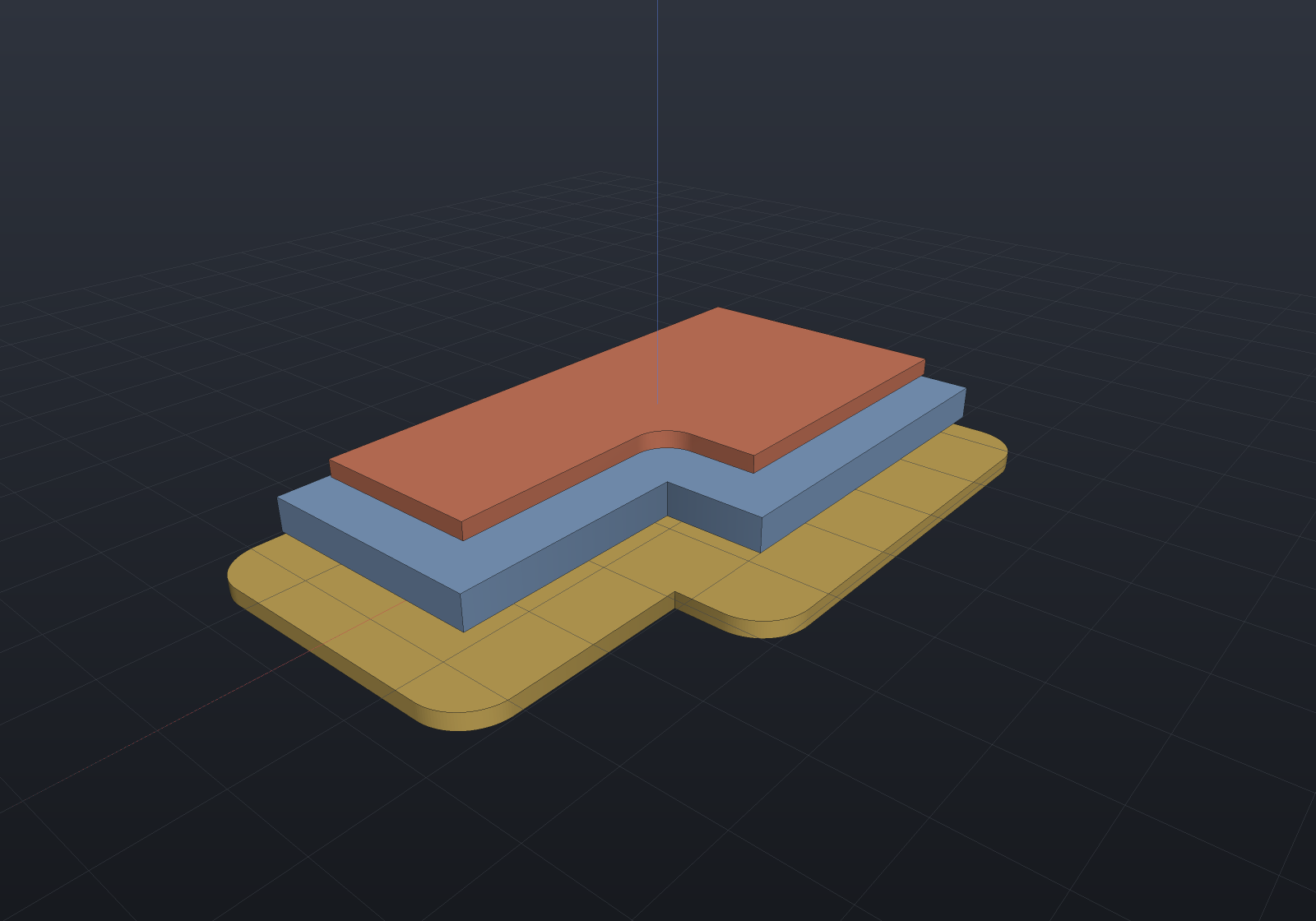
Offsetting is one algorithm, not two: the outward offset is the region unioned with a
slab per edge and a join per corner, and the inward offset is that same dilation
applied to the complement. Self-intersection therefore falls out rather than needing a
cleanup pass — shrink a plate through a narrow neck and you get two regions back, or
none at all if it vanishes. That is why Offset returns a list.
// A dumbbell: two 10-wide pads joined by a 3-wide neck. Shrink past the neck and the// one region becomes two; shrink past the pads and nothing is left.var bar = Sketch.Start(-15, -5).LineTo(-5, -5).LineTo(-5, -1.5).LineTo(5, -1.5)                .LineTo(5, -5).LineTo(15, -5).LineTo(15, 5).LineTo(5, 5)                .LineTo(5, 1.5).LineTo(-5, 1.5).LineTo(-5, 5).LineTo(-15, 5).Close();
if (bar.Offset(-1).Count != 1) throw new Exception("still one piece at -1");if (bar.Offset(-2).Count != 2) throw new Exception("the 3-wide neck should part at -2");if (bar.Offset(-6).Count != 0) throw new Exception("nothing should survive -6");
Stroking an open path
Region2dOffset.Stroke(path, width, cap, join) sweeps an open polyline into a
region of constant width — a toolpath’s footprint, a slot from its centre line, an
SVG stroke. Caps are Butt/Round/Square; joins are the same styles as Offset,
and because it is the same union-of-primitives construction, self-crossing paths and
doubled-back reversals need no special handling — with round caps and joins the
stroke is exactly the path’s Minkowski sum with a disk:
// A zig-zag clearing pass, stroked to the cutter's 3 mm diameter and extruded.var pass = new List<Vector2d>();for (int i = 0; i <= 6; i++){    double x = -18 + i * 6;    pass.Add(new Vector2d(x, i % 2 == 0 ? -10 : 10));}var swept = Region2dOffset.Stroke(pass, width: 3);
var scene = new Scene();scene.Add(new Part("stock", Shape.Box(48, 30, 4), Palette.Steel));foreach (var (region, i) in swept.Select((r, i) => (r, i))){    var (outer, holes) = Profile.FromRegion(region);    scene.Add(new Part($"pass {i}", Shape.Extrude(outer, Vector3d.UnitZ * 3, holes)        .Translate(0, 0, 2), Palette.Brass));}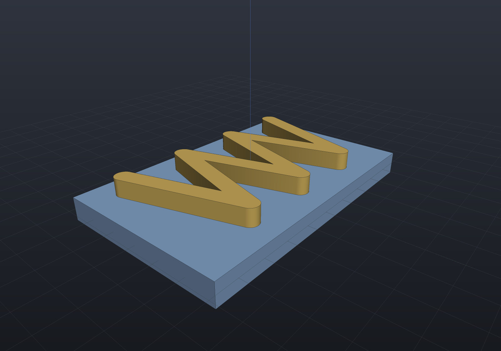
Closed circuits work by repeating the first point — the stroke then encloses a hole (one region, one hole), which is how a contour pass differs from a pocket.
Stroking a CURVED path
Region2dOffset.Stroke takes points, so an arc has to be flattened before it reaches
one — and the deficit that leaves is a floor, not a tolerance: no chord count removes
it. CurvedRegion2dOffset.Stroke(path, width, cap, join) takes a chain of
CurvedEdge2d (lines and arcs) instead and keeps every primitive closed form. An arc’s
slab is the annular sector between radii r ± width/2, a round cap is an exact
half-disc, and a round join an exact sector — so with round caps and joins the result
is the path’s Minkowski sum with a disc, nothing inscribed, and the swept area of an
arc of radius r is exactly sweep·r·width plus one disc of radius width/2.
Two conveniences ride on the edge vocabulary. A chain that returns to its start is
recognized as a circuit, so its closing joint gets a corner join and no caps — where
the repeated-point spelling above cannot claim one, and a butt-capped closed polyline is
short by exactly that corner. And when width/2 reaches the arc’s own radius the band
swallows the centre, which is handled exactly rather than refused: the slab becomes the
pie sector of radius r + width/2.
// A slot whose centre line is a straight run into a quarter turn: stroked to width and// extruded through an exact profile, so the ends and the bend stay true arcs.var centreLine = new[]{    CurvedEdge2d.Line((-20, 0), (0, 0)),    CurvedEdge2d.Arc((0, 10), 10, -Math.PI / 2, Math.PI / 2),};var swept = CurvedRegion2dOffset.Stroke(centreLine, width: 6);
var scene = new Scene();scene.Add(new Part("plate", Shape.Box(64, 44, 4).Translate(-4, 6, 0), Palette.Steel));foreach (var (region, i) in swept.Select((r, i) => (r, i))){    var (outer, holes) = Profile.FromCurvedRegion(region);    scene.Add(new Part($"slot {i}", Shape.Extrude(outer, Vector3d.UnitZ * 3, holes)        .Translate(0, 0, 2), Palette.Brass));}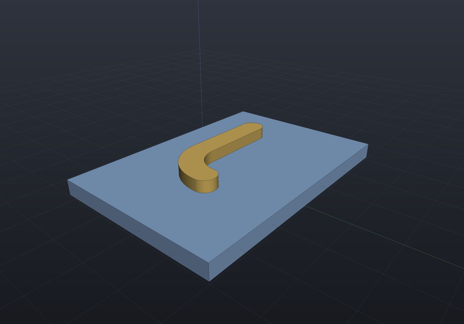
Section: projection(cut = true)
Shape.Section(plane) is the cross-section — the drawing-view section, and OpenSCAD’s
projection(cut = true). Cavities become holes automatically, including one with no
opening to the outside at all:
// Two through-bores and a SEALED internal cavity: a cylinder short enough that it never// reaches an end face, so the solid has a void with no opening at all.var block = Shape.Box(40, 24, 16)    .Drill(StandardHoles.Clearance(6), [new(-15, 0), new(15, 0)], depth: 20,           SketchPlane.At((0, 0, 8), Vector3d.UnitX, Vector3d.UnitY))    - Shape.Cylinder(4, 20).Rotate(Vector3d.UnitY, Math.PI / 2);
// Slice at z = 0 and re-extrude the section as a thin plate to show what came back.var slice = block.Section(SketchPlane.At((0, 0, 0), Vector3d.UnitX, Vector3d.UnitY));
var scene = new Scene();scene.Add(new Part("block", block, Palette.Slate, Matrix4d.CreateTranslation((0, 26, 0))));foreach (var (region, i) in slice.Select((r, i) => (r, i))){    var (outer, holes) = Profile.FromRegion(region);    scene.Add(new Part($"section {i}", Shape.Extrude(outer, Vector3d.UnitZ * 1.5, holes),        Palette.Brass, Matrix4d.CreateTranslation((0, -14, 0))));}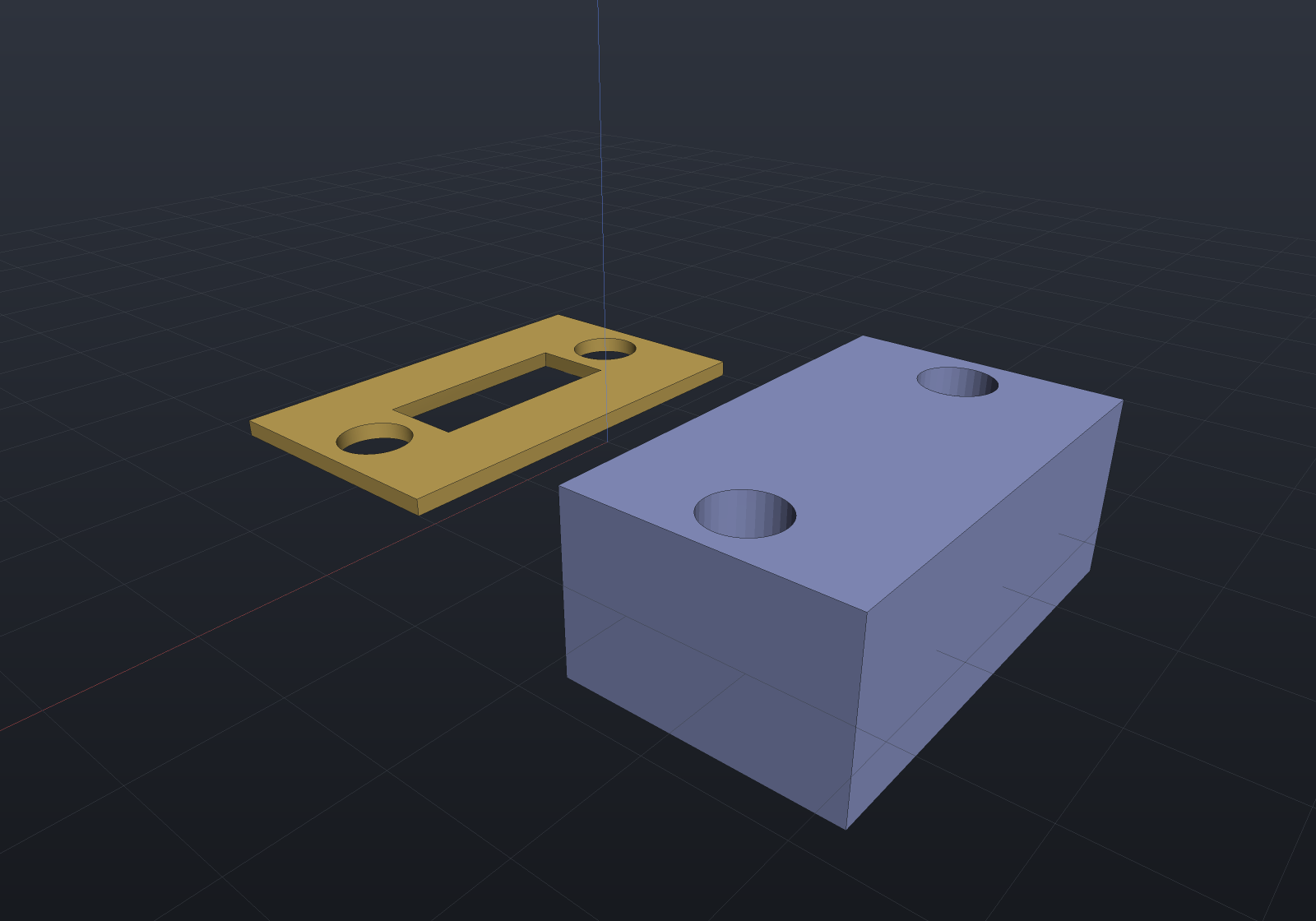
When the shape lowers to B-Rep the section is taken from the exact surfaces, so its fidelity is set by the chord tolerance alone — a bore rim is as round as you ask for, not as round as the display mesh happens to be. Shapes with no B-Rep form fall back to the mesh.
A plane flush with a face, or containing an edge, is refused: a section that runs along a face is an area, not a curve. Move the plane a fraction.
SectionExact: the same section without the flattening
Shape.SectionExact(plane) returns CurvedRegion2ds instead, so a bore’s
rim is one arc rather than however many chords a tolerance asked for — which is what a
DXF CIRCLE entity, an SVG A command and Sketch.FromCurvedRegion all want. It is the
same pipeline: the same edge crossings, the same containment probes, the same chaining,
with only the emit differing.
var plate = Shape.Box(60, 40, 10)    .Drill(HoleSpec.Simple(8), [new(-15, 0), new(15, 0)], depth: 20,           SketchPlane.At((0, 0, 5), Vector3d.UnitX, Vector3d.UnitY));var mid = SketchPlane.At((0, 0, 0), Vector3d.UnitX, Vector3d.UnitY);
var exact = plate.SectionExact(mid);double area = exact.Sum(r => r.Area);double truth = 60.0 * 40 - 2 * Math.PI * 16;      // πr² per bore, exactlyif (Math.Abs(area - truth) > 1e-9)    throw new Exception("an exact section is the closed form");
// The flattened route leaves an inscribed polygon, which is a FLOOR rather than a// tolerance: it is over by the n-gon's own deficit however fine the chords get.if (!(plate.Section(mid).Sum(r => r.Area) > truth))    throw new Exception("an inscribed polygon leaves more material than the circle");
What it cannot express exactly it flattens rather than refusing: an oblique plane
through a cylinder cuts an ellipse, which the curved 2D tier deliberately does not carry,
and a traced intersection is a polyline to begin with. So a mixed section is honest, and
its exact halves stay exact. Silhouette has no such mode at all, and that is structural:
it is the union of projected triangles, so there is nothing exact to recover.
A plane FLUSH with a face
A plane containing a whole face has no cross-section curve at all — the intersection there is an area — so it is refused by default. What it should answer instead is a genuine question with three different right answers, so the primitive is the pair of limits and the caller says which it means.
The fixture that settles it is a fused step block: a slab of footprint A under a
boss of footprint B ⊂ A, sectioned exactly at the step.
var stepBlock =    Shape.Box(40, 30, 10).Translate(0, 0, 5)    | Shape.Box(20, 15, 10).Translate(0, 0, 15);
var step = new SketchPlane(Frame3d.FromOrthonormal(    new Vector3d(0, 0, 10), Vector3d.UnitX, Vector3d.UnitY));
var limits = PlanarSection.FlushLimitsOf(stepBlock.ToBrep(), step.Frame);double below = limits.Below.Sum(r => r.Area);     // 1200 — the whole slabdouble above = limits.Above.Sum(r => r.Area);     //  300 — just the bossdouble union = limits.Union().Sum(r => r.Area);   // 1200 — the set-theoretic solid ∩ plane
if (Math.Abs(below - 1200) > 1e-6 || Math.Abs(above - 300) > 1e-6)    throw new Exception("the two limits are the slab and the boss");
// The answer nothing here may return is 900 = A∖B, which is what letting flush faces// contribute their own regions produces — a region NEITHER limit ever takes.foreach (double area in new[] { below, above, union })    if (Math.Abs(area - 900) < 1) throw new Exception("that is A∖B, not a limit");
var scene = new Scene();scene.Add(new Part("step block", stepBlock));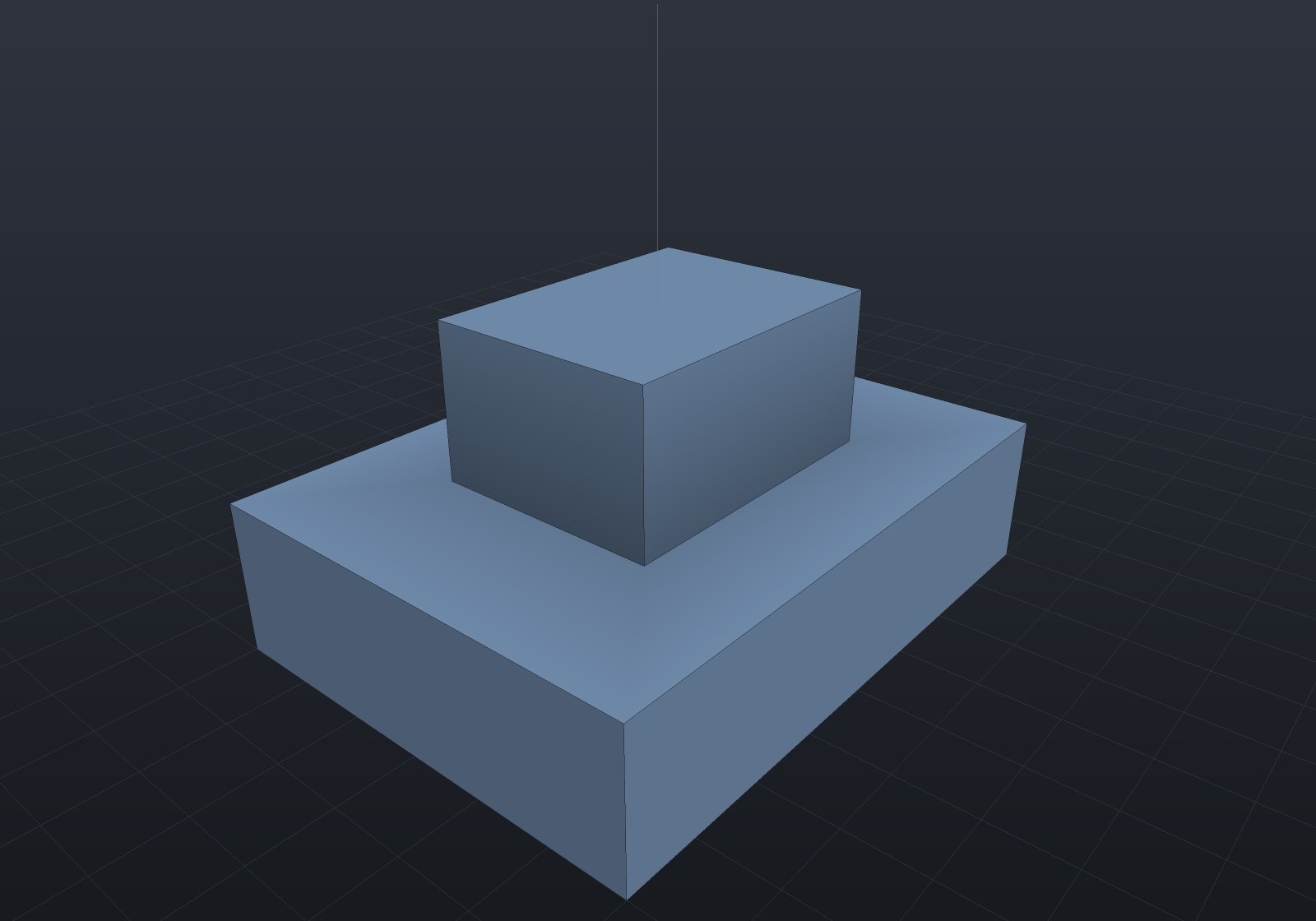
Shape.Section and Shape.SectionExact take the same choice:
var stepBlock =    Shape.Box(40, 30, 10).Translate(0, 0, 5)    | Shape.Box(20, 15, 10).Translate(0, 0, 15);var step = new SketchPlane(Frame3d.FromOrthonormal(    new Vector3d(0, 0, 10), Vector3d.UnitX, Vector3d.UnitY));
double slab = stepBlock.Section(step, flush: FlushSection.Below).Sum(r => r.Area);double boss = stepBlock.Section(step, flush: FlushSection.Above).Sum(r => r.Area);if (Math.Abs(slab - 1200) > 1e-6 || Math.Abs(boss - 300) > 1e-6)    throw new Exception("the policy routes through the same limits");
// The default still refuses, and names the way through.try{ stepBlock.Section(step); throw new Exception("a flush plane must refuse by default");}catch (NotSupportedException) { }| Policy | What it means |
|---|---|
FlushSection.Refuse | The default, and every call that already existed. |
FlushSection.Below / Above | One limit — what a drawing’s section view wants when you know which side you are looking at. |
FlushSection.Union | The set-theoretic solid ∩ plane, which is what OpenSCAD’s projection(cut = true) means. It is derived from the pair, not a fourth answer. |
Each limit is an ordinary exact transversal section of its own plane, nudged by a
fraction of the model’s own diagonal. Where the boundary is a vertical wall — which is
what a flush face makes — the section is identical for every small nudge and the limit is
reproduced exactly; where a wall is sloped it differs by δ·tan(slope), and
FlushLimits.Nudge reports the δ that was spent.
Silhouette: projection(cut = false)
Shape.Silhouette(plane) is the outline the shape casts along the plane’s normal — the
shadow, not the slice. A through hole survives as a hole; a blind pocket does not,
because there is material in front of it:
var bracket = Shape.Box(36, 20, 8)    .Drill(StandardHoles.Clearance(5), [new(-13, 0), new(13, 0)], depth: 12,           SketchPlane.At((0, 0, 4), Vector3d.UnitX, Vector3d.UnitY))    | Shape.Cylinder(7, 18).Translate(0, 0, 9);
var scene = new Scene();scene.Add(new Part("bracket", bracket, Palette.Sage, Matrix4d.CreateTranslation((0, 34, 0))));
void AddOutline(string name, SketchPlane plane, PartColor color, Vector3d at){    foreach (var (region, i) in bracket.Silhouette(plane).Select((r, i) => (r, i)))    {        var (outer, holes) = Profile.FromRegion(region);        scene.Add(new Part($"{name} {i}", Shape.Extrude(outer, Vector3d.UnitZ * 1, holes),            color, Matrix4d.CreateTranslation(at)));    }}
AddOutline("top", SketchPlane.XY, Palette.Steel, (0, 6, 0));    // bores surviveAddOutline("front", SketchPlane.XZ, Palette.Coral, (0, -18, 0)); // boss appears, bores do not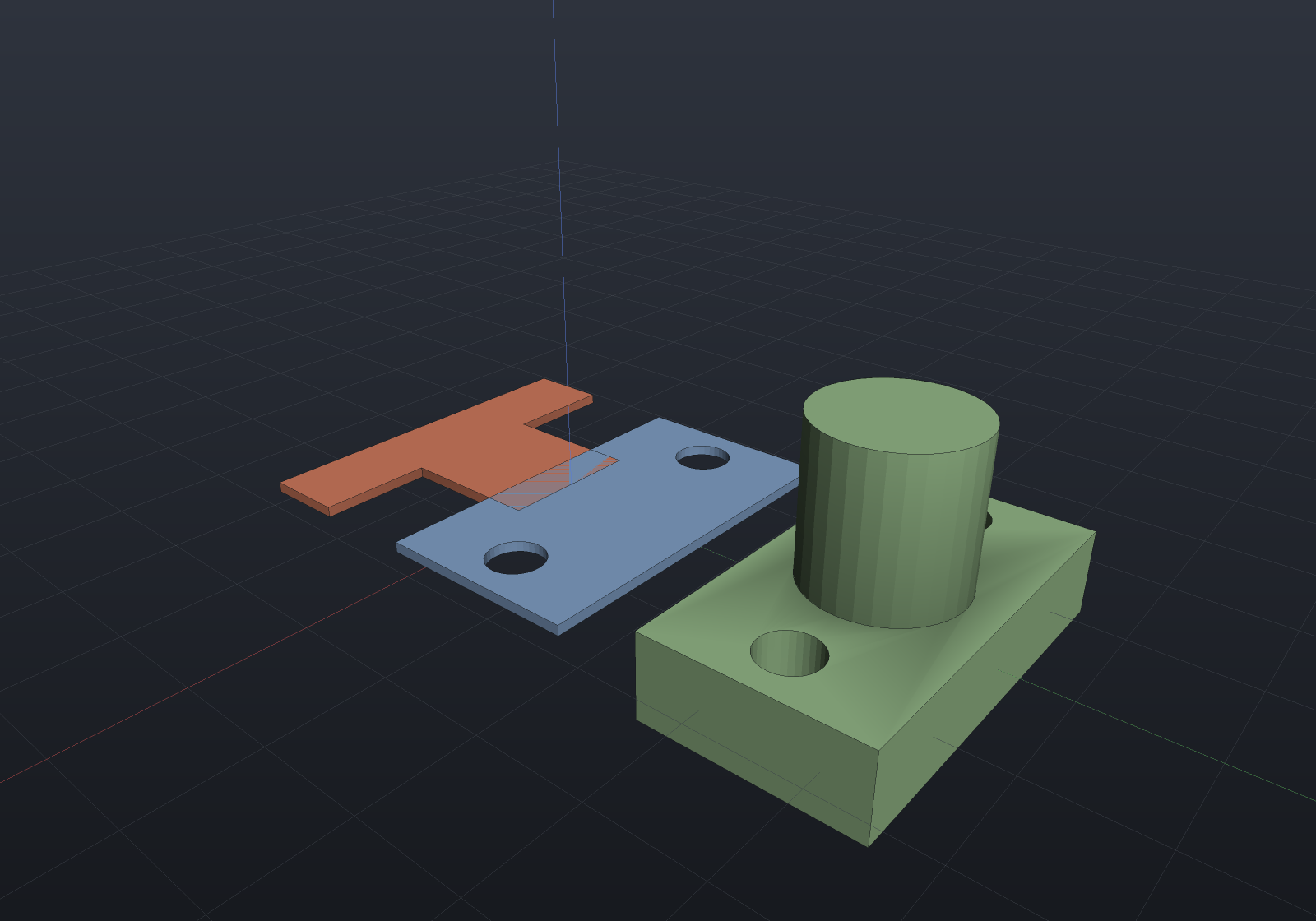
The two views say different things, and both are right. Looking down, the bores go all the way through, so they survive as holes and the boss adds nothing (it sits inside the plate’s footprint). Looking from the front, the boss becomes the stem of a T — and the bores vanish, because along that direction there is material in front of them.
A silhouette is the union of every front-facing projected triangle, so it is a mesh result — its fidelity is the mesh’s, and a finer mesh costs more union work. The unions are folded through a balanced tree over Morton-sorted faces, which is not a micro-optimization: on a 64-segment torus that is 67 ms against 2.4 s for the same tree unsorted and 259 s accumulated linearly. Merging face 1 with face 900 produces two disjoint regions and cancels nothing.
The wedge primitive
Shape.Wedge(sizeX, sizeY, sizeZ, topX, topOffsetX) is OCCT’s BRepPrimAPI_MakeWedge
and the last primitive OpenSCAD reaches for polyhedron to build. The base is
sizeX × sizeY; the top keeps the same y but is topX wide, centred at topOffsetX:
var scene = new Scene();scene.Add(new Part("chisel", Shape.Wedge(16, 12, 10), Palette.Steel, Matrix4d.CreateTranslation((-22, 0, 0))));scene.Add(new Part("ramp", Shape.Wedge(16, 12, 10, topX: 0, topOffsetX: 8), Palette.Brass));scene.Add(new Part("dovetail", Shape.Wedge(16, 12, 10, topX: 24), Palette.Sage, Matrix4d.CreateTranslation((24, 0, 0))));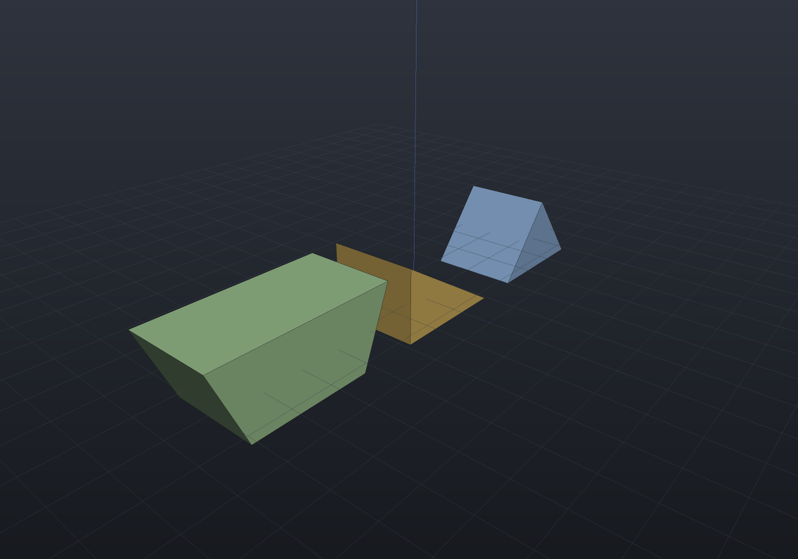
topX: 0 gives a sharp top edge; moving it over one side with topOffsetX: ±sizeX/2
gives the classic ramp (a right triangular prism); a topX larger than sizeX gives a
dovetail rail. The taper is in x only — a solid tapering in both directions is a loft,
not a wedge.
A wedge is an extrusion (a trapezoidal cross-section swept along y), so it carries one internally and every lowering delegates to it. That is why it is native in all three representations for free, and exact under any affine transform.
Exactness
Most of this page is polygonal: the Region2d arrangement the boolean runs on carries
segments, not arcs, so curves reach it flattened at a chord tolerance. A circle offset
outward by d then lands just inside π(r+d)² — round joins are inscribed arcs,
matching Sketch.ToRegions’s one-sided contract, so errors never accumulate in the
unsafe direction.
The curved tier removes that step where the geometry is lines and arcs.
CurvedRegion2d and its arrangement carry arcs unflattened, so a disc measures exactly
πr², CurvedRegion2dBoolean returns arcs, CurvedRegion2dOffset’s round joins are
exact sectors, and Profile.FromCurvedRegion turns the result into analytic arcs
rather than chords — an extruded sketch boolean becomes an exact B-Rep instead of a
prism of chords. From the Sketch API the entry points are UnionExact,
IntersectExact, SubtractExact and OffsetExact. What the tier does not carry is
Béziers and general NURBS: they are still flattened at the entry points, stated in the
API contract rather than hidden, because the cell walk’s tangent-plus-curvature
tie-break is decidable for lines and circles and not for a third shape.