Holes & standard sizes
Shape.Drill(hole, points, depth, plane?) places one hole recipe at a list of 2D
points on a sketch plane, cutting along −normal. Every tool is an axis-touching
revolved sketch, so drilling is exact in all three representations.
Explicit dimensions
HoleSpec.Simple, Counterbore, and Countersink take explicit dimensions:
var top = SketchPlane.At((0, 0, 6), Vector3d.UnitX, Vector3d.UnitY);
var plate = Shape.Box(60, 30, 12)    .Drill(HoleSpec.Simple(6), [new(-20, 0)], depth: 14, top)    .Drill(HoleSpec.Counterbore(5, counterboreDiameter: 10, counterboreDepth: 4),           [new(0, 0)], depth: 14, top)    .Drill(HoleSpec.Countersink(5, countersinkDiameter: 11), [new(20, 0)], depth: 14, top);
var scene = new Scene();scene.Add(new Part("drilled plate", plate, Palette.Steel,    Matrix4d.CreateTranslation((0, 0, 6))));    // rest the plate on the ground plane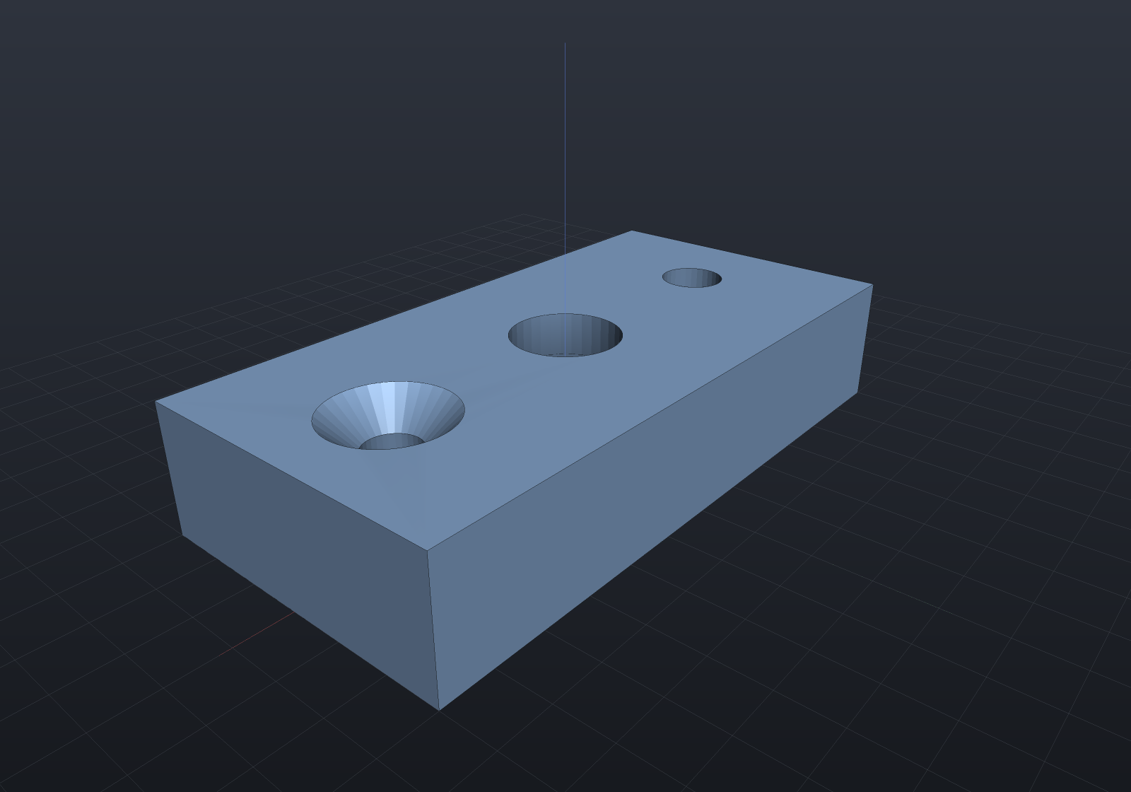
A depth past the far side gives a through-hole; a shorter depth gives a blind hole with a flat bottom. The tools overshoot the surface so the booleans never see coplanar faces, and the countersink cone continues its slope past the surface so the surface diameter stays exact.
Drill points
A real twist drill leaves a cone at the bottom of a blind hole.
spec.WithTipAngle(degrees) models it — StandardHoles.TwistDrillPoint is the
general-purpose 118°, SplitDrillPoint the 135° of split-point drills:
var top = SketchPlane.At((0, 0, 6), Vector3d.UnitX, Vector3d.UnitY);var flat = HoleSpec.Simple(6);var drilled = flat.WithTipAngle(StandardHoles.TwistDrillPoint);
var plate = Shape.Box(60, 30, 12)    .Drill(flat, [new(-15, 0)], depth: 7, top)       // flat bottom: reamed or bored    .Drill(drilled, [new(15, 0)], depth: 7, top);    // 118 degrees: as drilled
// Both bores are 7 mm deep to the SHOULDER; the point reaches further.var sectioned = Shape.From(plate.ToImplicit())    - Shape.Box(62, 32, 16).Translate(0, 16, 0);
var scene = new Scene(new MeshQuality { SdfResolution = 160 });scene.Add(new Part("flat and drilled bottoms", sectioned, Palette.Copper,    Matrix4d.CreateTranslation((0, 0, 6))));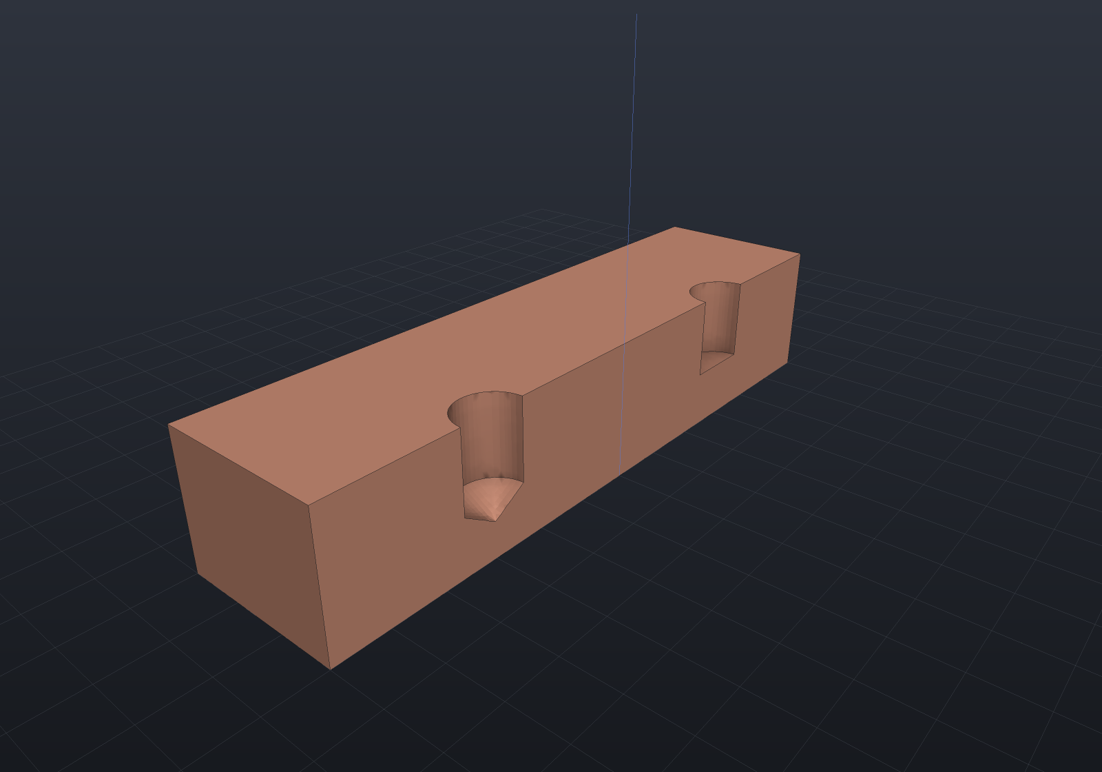
Depth is measured to the shoulder — the deepest full-diameter point — with the tip
reaching (diameter / 2) / tan(angle / 2) further, which is how a drawing dimensions a
blind hole. So adding a point is strictly additive: the same depth removes the same
cylinder either way, plus the cone. spec.TipLength reports the overhang, which is the
number to check against the far face — a blind depth that cleared it may not once the
point is there. The default stays flat, so existing designs are unchanged and a through
hole (where the point never survives into the finished part) needs nothing.
A blind hole that breaks out of a face
Drilling near an edge is ordinary practice, and a blind bore’s flat bottom can end up crossing the face the bore has already broken out of. Both faces cut cleanly:
var wall = SketchPlane.At((0, -15, 9), Vector3d.UnitX, Vector3d.UnitZ);
var plate = Shape.Extrude(Sketch.Rectangle(40, 30), 10)    .Drill(HoleSpec.Simple(6), [new(0, 0)], depth: 15, wall);   // in from the front wall
var camera = new CameraState(-Math.PI / 2 + 0.6, 0.45, 90, (0, 0, 4));var scene = new Scene();scene.Add(new Part("blind bore off the top edge", plate, Palette.Steel));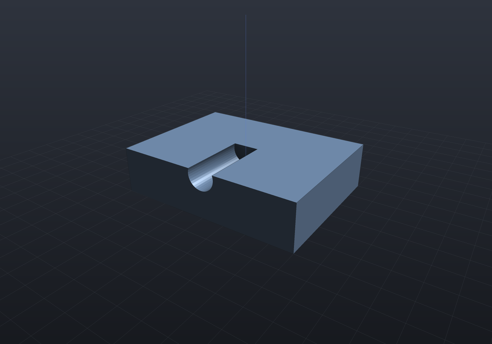
The bore’s axis sits 1 mm below the top face and its radius is 3, so the hole opens into a
slot along the top — and because it is BLIND, the tool’s flat end stops inside the plate
and that end is cut by the top face too. The removed volume converges quadratically onto
the analytic disc-less-a-segment figure, and onto the same cut made with a plain
Shape.Cylinder.
A bore whose axis lands exactly on the face it breaks out of works too, and it is the hardest member of the family rather than the easiest: the flat end is then cut along a full diameter, straight through the one point of that face where its own parameterization — an azimuth about the pole — does not exist.
var level = SketchPlane.At((0, -15, 10), Vector3d.UnitX, Vector3d.UnitZ);   // axis ON the top face
var halved = Shape.Extrude(Sketch.Rectangle(40, 30), 10)    .Drill(HoleSpec.Simple(6), [new(0, 0)], depth: 15, level);
// Exactly half the bore is inside the plate, so the removal is (pi * 3^2 / 2) * 15.var removed = 40 * 30 * 10 - BrepMassProperties.Compute(halved.ToBrep()).Volume;Console.WriteLine($"{removed:F2} removed");   // 212.06 removed
The remaining limit is a grazing breakout, and it is now a genuine near-tangency rather
than a property of the drill: on the plate above, an opening down to about 0.5 mm across
(a quarter of a millimetre either side of the bore’s top) cuts cleanly, and below that the
bore’s own entry rim becomes tangent to the plate’s top edge — a circle touching a line —
which is where the exact boolean stops by design. The same cut made with a plain
Shape.Cylinder stops at the same place, which is what says it is the configuration rather
than the tool. Past it the boolean fails loudly rather than returning a solid with a crack
in it, and the implicit route (Shape.From(shape.ToImplicit()).ToMesh()) takes any of them.
The standards catalog
StandardHoles (metric, mm) supplies ISO 273 clearance fits, DIN 974-style
counterbores for socket cap screws, 90° countersinks for ISO 10642 flat-heads, coarse
tap pilot holes, and Tappex Trisert® insert pilots:
var top = SketchPlane.At((0, 0, 6), Vector3d.UnitX, Vector3d.UnitY);
var plate = Shape.Box(30, 20, 12)    .Drill(StandardHoles.Countersunk(3), [new(-10, 5)], depth: 14, top)   // M3 flat-head    .Drill(StandardHoles.Counterbored(4), [new(0, 5)], depth: 14, top)    // M4 socket cap    .Drill(StandardHoles.Clearance(5), [new(10, 5)], depth: 14, top)      // M5 clearance    .Drill(StandardHoles.Tapped(6), [new(-5, -5)], depth: 10, top)        // M6 tap pilot (blind)    .Drill(StandardHoles.Trisert(4), [new(5, -5)],           StandardHoles.TrisertMinimumDepth(4), top);                    // M4 insert pilot
var scene = new Scene();scene.Add(new Part("standard holes", plate, Palette.Brass,    Matrix4d.CreateTranslation((0, 0, 6))));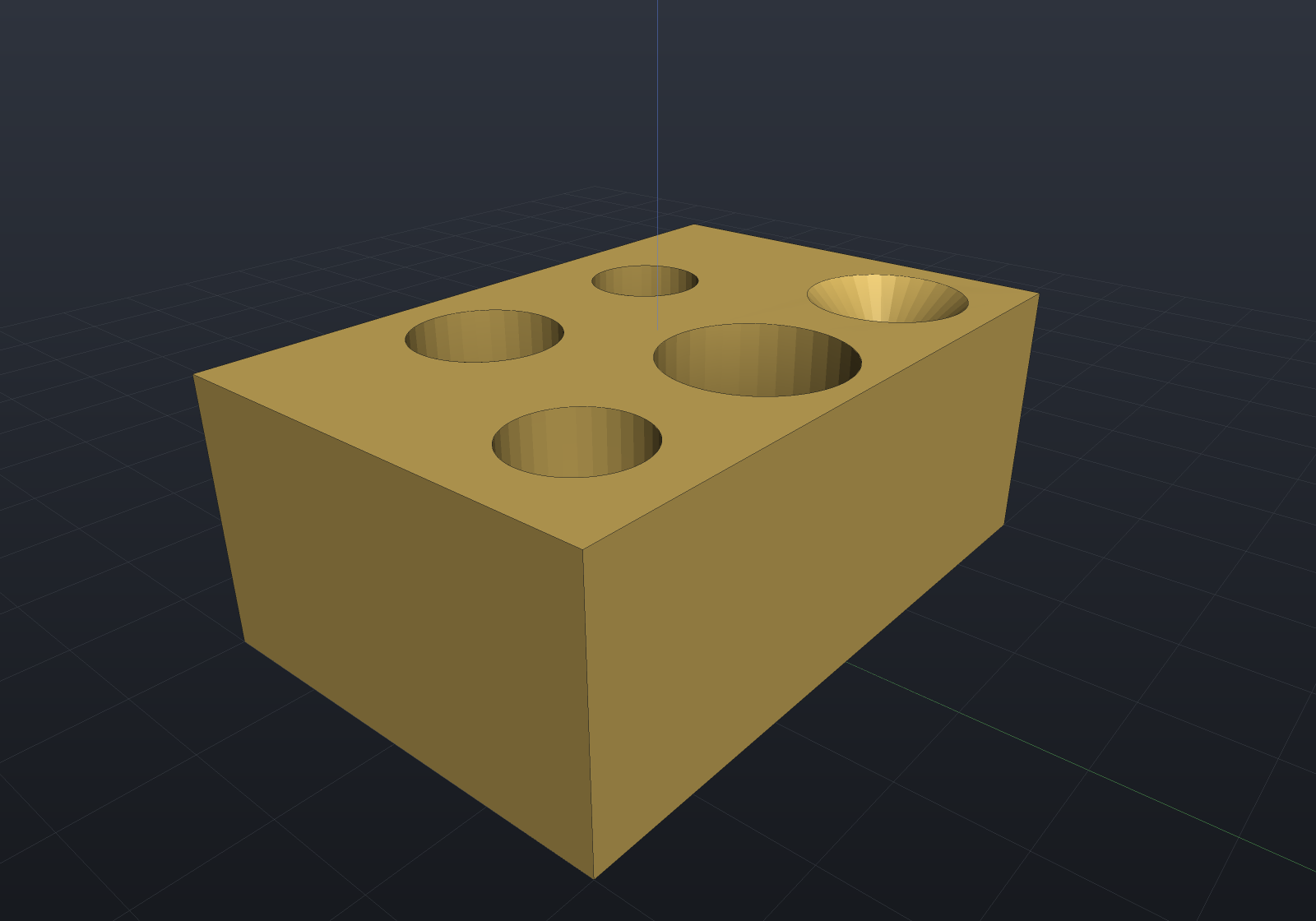
Clearance takes a ClearanceFit (Close/Normal/Loose); Tapped models the
pilot hole only — for real modeled thread geometry see threads.
⚠ The Trisert table should be verified against the current Tappex datasheet before
production use.
Seeing inside
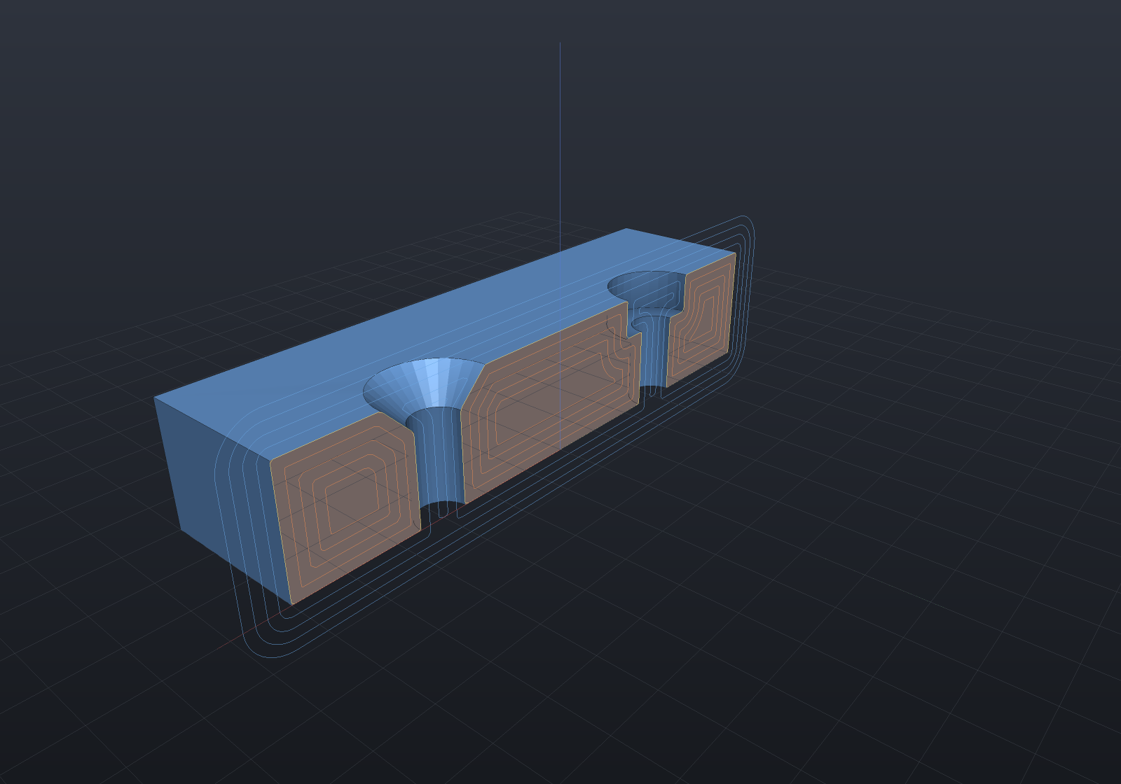
A real section plane through the hole axes shows the counterbore step and
countersink cone the recipes produce — the same cut the viewer’s
section mode makes interactively, here as a render option (section:y,0
on the fence), so the geometry stays the exact B-Rep and the cut faces shade as flat
cut material. The contour rings on the cut are the automatic
SDF isolines — drilling is exact in the
implicit engine too, and the gold ring is the exact surface cross-section:
var top = SketchPlane.At((0, 0, 6), Vector3d.UnitX, Vector3d.UnitY);
var plate = Shape.Box(60, 30, 12)    .Drill(HoleSpec.Counterbore(5, 10, 4), [new(-15, 0)], depth: 14, top)    .Drill(HoleSpec.Countersink(5, 11), [new(15, 0)], depth: 14, top);
var scene = new Scene();scene.Add(new Part("plate", plate, Palette.Sky,    Matrix4d.CreateTranslation((0, 0, 6))));