Composites (laminates & failure criteria)
A composite part is directional twice over: it is stiffer along the fibre than across
it, which ElasticLaw already carries, and it is stronger along
the fibre than across it, which no scalar equivalent stress can express. This page covers
the two things that follow — turning a layup into a constitutive law with classical
lamination theory, and measuring the recovered stress against per-direction allowables.
[!IMPORTANT]
MaxVonMiseson a composite part is a number with no engineering meaning. A scalar equivalent stress compares a state against one allowable, which presumes the material is equally strong in every direction. A carbon/epoxy ply is 37× stronger along the fibre than across it — 1500 MPa against 40 — so the same von Mises number can be comfortably safe in one direction and well past failure in another. UseFailureAnalysis.
A laminate is a property derivation
Laminate is a stack of plies and the classical lamination theory over it. It adds no
element type and no solver path: it produces an ElasticLaw, which rides
StructuralModel.SetElasticity exactly as a hand-stated orthotropic law does.
// T300/5208 graphite/epoxy - the canonical row (verify against a real data sheet).var t300 = new LaminaProperties(e1: 181_000, e2: 10_300, nu12: 0.28, g12: 7_170, name: "T300/5208");
// [0/90]s - Symmetric() appends the mirror image, so this is 0/90/90/0.var crossPly = Laminate.Symmetric(t300, plyThickness: 0.125, 0.0, 90.0);
Console.WriteLine($"h = {crossPly.Thickness} mm, symmetric = {crossPly.IsSymmetric}, "    + $"balanced = {crossPly.IsBalanced}");Console.WriteLine($"in-plane  Ex {crossPly.InPlane.Ex:F0}  Ey {crossPly.InPlane.Ey:F0}  "    + $"Gxy {crossPly.InPlane.Gxy:F0} MPa,  nu_xy {crossPly.InPlane.NuXy:F4}");Console.WriteLine($"flexural  Ex {crossPly.Flexural.Ex:F0}  Ey {crossPly.Flexural.Ey:F0} MPa");Console.WriteLine($"smearing cost (flexural discrepancy) {crossPly.FlexuralDiscrepancy:F3}");
// The ABD matrices are there in the textbook's own terms - 3x3 row-major over (x, y, xy).Console.WriteLine($"A11 = {crossPly.A[0]:F1} N/mm, A16 = {crossPly.A[2]:F1} (exactly zero)");
if (crossPly.A[2] != 0.0 || crossPly.A[5] != 0.0)    throw new Exception("a cross-ply has no shear-extension coupling");
Which prints:
h = 0.5 mm, symmetric = True, balanced = Truein-plane Ex 95991 Ey 95991 Gxy 7170 MPa, nu_xy 0.0302flexural Ex 160114 Ey 31727 MPasmearing cost (flexural discrepancy) 0.401A11 = 48039.3 N/mm, A16 = 0.0 (exactly zero)Three of those numbers are worth reading twice. Gxy is the lamina’s own 7170 MPa —
cross-plying does nothing for shear, because a 0° ply and a 90° ply have the same Qbar66.
nu_xy collapses to 0.0302 because the 90° plies restrain the contraction the 0° plies
want. And the flexural Ex is 1.67× the in-plane one, which is the next section.
| Layup | Ex (MPa) | Gxy (MPa) | nu_xy |
|---|---|---|---|
[0]₄ unidirectional | 181 000 | 7 170 | 0.280 |
[0/90]s cross-ply | 95 991 | 7 170 | 0.030 |
[±45]s angle-ply | 25 051 | 46 591 | 0.747 |
[0/45/-45/90]s quasi-isotropic | 69 676 | 26 880 | 0.296 |
The [±45]s row is the reason that layup exists: its shear modulus is 6.5× the lamina’s,
because ±45 fibres carry shear as tension. Its Poisson’s ratio of 0.747 is not a mistake
either — the isotropic bound of 0.5 is a statement about isotropic materials.
What smearing drops, as a number
A solid element carrying one constitutive law has no memory of the stacking sequence through its thickness. Two consequences, both reported rather than implied:
- Bending–extension coupling cannot be represented at all. A non-symmetric layup has a
non-zero
Bmatrix — in-plane load produces curvature — andToElasticLaw()refuses it by name rather than returning a law that is quietly wrong about warping. - Flexural stiffness survives only to the extent that
Dagrees withh²·A/12.FlexuralDiscrepancymeasures exactly that gap: 0.401 for the[0/90]sabove, because its outer 0° plies dominate the section modulus and the smearing does not know they are outside. A plate model of that laminate under bending will be wrong by about that much.
Both have the same way out: mesh the plies as separate regions through the thickness and
give each its own ElasticLaw. Interlaminar stress and delamination are outside the smeared
model entirely — it has no ply interfaces to separate.
What the smearing does not cost is in-plane accuracy. The homogenisation is mixed —
plies share the in-plane strain (they are bonded) and share the through-thickness stress
(they stack), which is the same parallel/series split the PCB thermal
model rests on — and condensing the resulting 6×6 back to plane stress
returns A/h exactly. A solved bar reproduces the CLT modulus to nine digits:
95 991.30 MPa against 95 991.30.
Failure criteria
FailureAnalysis.Evaluate rotates the recovered stress into the material frame — the
one the region’s own ElasticLaw was built with, never a second copy that could drift —
and measures it against a LaminaStrength.
var plate = Shape.Box(60, 40, 8)    .Subtract(Shape.Cylinder(6, 40).Translate(0, 0, -20));var part = new Part("panel", plate);
var surface = part.GetMesh();var tets = TetMesher.Mesh(surface, new TetMeshOptions{    RefineQuality = true,    MaxElementSize = 14,     // coarse on purpose - this page is a picture, not a study});
// A quasi-isotropic layup, 8 plies of 1 mm: [0/45/-45/90]s.var t300 = new LaminaProperties(181_000, 10_300, 0.28, 7_170, name: "T300/5208");var layup = Laminate.Symmetric(t300, 1.0, 0.0, 45.0, -45.0, 90.0);
var model = new StructuralModel(    AnalysisMesh.Quadratic(tets), new Material("T300/5208", 70_000, 0.3, 1.6e-9));
// The laminate's 0-degree direction is +X and it stacks along +Z.model.SetElasticity(0, layup.ToElasticLaw(Frame3d.WorldXY));model.SetStrength(0, new LaminaStrength(xt: 1500, xc: 1500, yt: 40, yc: 246, s: 68));
model.Fix(Facets.OnPlane(new Vector3d(-30, 0, 0), Vector3d.UnitX));model.Traction(Facets.OnPlane(new Vector3d(30, 0, 0), Vector3d.UnitX), new Vector3d(45, 0, 0));
var results = StructuralSolver.Solve(model);var failure = FailureAnalysis.Evaluate(results, FailureCriterion.TsaiWu);
Console.WriteLine($"peak failure index {failure.MaxFailureIndex:F3}, "    + $"strength ratio {failure.MinStrengthRatio:F3}, "    + $"out-of-plane fraction {failure.MaxOutOfPlaneFraction:E1}");if (!(failure.MaxFailureIndex > 0))    throw new Exception("the criterion found nothing to measure");
foreach (var field in failure.SampleOnto(surface))    part.AddResult(field);part.FieldDisplay = new FieldDisplay { Field = FailureResults.FieldNames.FailureIndex };
var scene = new Scene();scene.Add(part);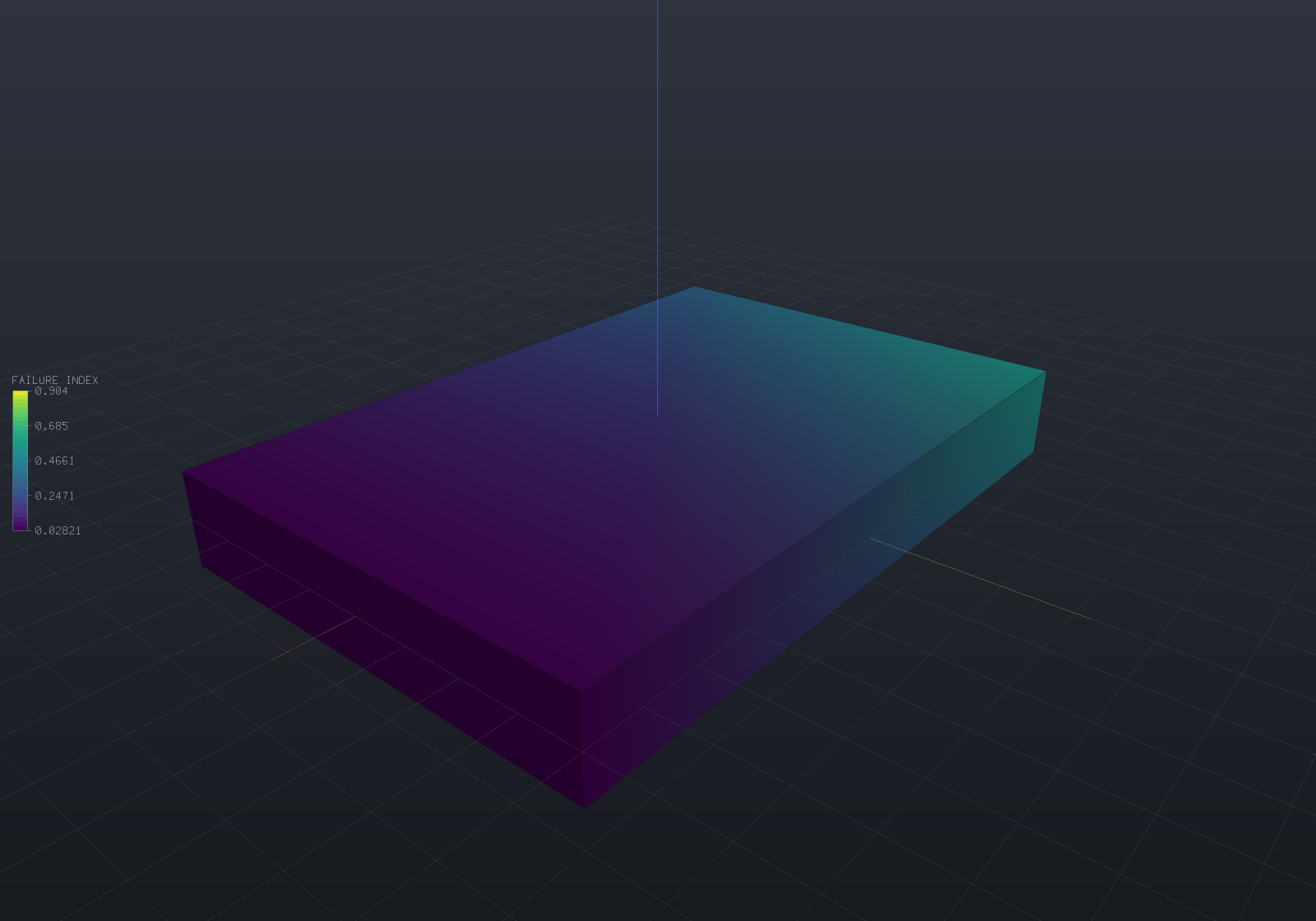
The colour is the failure index: 1 is exactly at the limit, above 1 has failed. This panel
peaks at 0.968 — inside the envelope, with 3% left — so MinStrengthRatio reads 1.033 and the
load could rise by 3% before Tsai–Wu says the laminate is done. Note what a von Mises plot of
the same solve could not have told you: at 45 MPa of applied tension the quasi-isotropic
laminate is nowhere near its 1500 MPa fibre strength, and it is still almost at its limit,
because the 90° plies are carrying transverse stress against a 40 MPa allowable.
Three criteria, and what separates them
| Criterion | Interaction | Names a mode | Tension ≠ compression |
|---|---|---|---|
MaxStress | none | yes | yes (per component) |
TsaiHill | quadratic | no | by the sign of each component |
TsaiWu | quadratic + linear | no | continuously |
They agree exactly on the five uniaxial tests they are all calibrated on — a pure
fibre-direction tension reaches failure at exactly Xt for all three — and diverge in the
interior. At σ₁ = 900, σ₂ = 25, τ₁₂ = 40 MPa, max-stress reads 0.625 while Tsai–Hill
reads 1.042 and Tsai–Wu 1.090: the non-interactive criterion calls a failed state
safe, which is the classic reason not to use it alone.
MaxStress earns its place by naming the mode, which is a real engineering distinction —
matrix cracking at Yt is a different event from fibre failure at Xt, and a designer treats
them differently. At σ₁ = 600, σ₂ = 30 the index is 0.750 and the mode is MatrixTension:
a transverse stress a twentieth the size of the fibre stress is what governs.
The index is load-normalised, not the raw polynomial
FailureIndex is 1 / StrengthRatio, not the quadratic’s left-hand side. That is what makes
the three criteria comparable with each other and linear in the load — and it makes the
strength ratio, R, the number an engineer actually wants: R = 2 means the load can
double. The definition is verified through the solver rather than restated: scale the
traction by R, re-solve, and the peak index lands on 1.000000000000 for all three criteria.
Off-axis strength
A unidirectional lamina pulled at an angle to its fibres has a strength that collapses astonishingly fast, and both criteria reproduce their classical closed forms exactly:
| Angle | Max-stress (MPa) | Tsai–Hill (MPa) |
|---|---|---|
| 0° | 1500.00 | 1500.00 |
| 15° | 272.00 | 244.85 |
| 30° | 157.04 | 111.96 |
| 45° | 80.00 | 68.95 |
| 90° | 40.00 | 40.00 |
Ten degrees off the fibre throws away three quarters of the strength (1500 → 370 MPa). That is the whole argument for a laminate rather than a unidirectional layup.
The interaction coefficient is a stated choice
Tsai–Wu’s F12* is the one coefficient no uniaxial test determines — measuring it needs a
biaxial test, and published values scatter. It is therefore a parameter with a stated default
(-0.5, the generalised von Mises choice) rather than a constant buried in the evaluator, and
the choice measurably moves the answer in the biaxial interior (R = 1.628 at −0.5 against
1.421 at 0) while leaving every uniaxial reduction untouched. |F12*| ≥ 1 is refused by name:
past that the failure surface opens into a hyperboloid and some arbitrarily large biaxial
state would be reported safe.
What is reported rather than consumed
The criteria are plane-stress: they read σ₁, σ₂ and τ₁₂ in the material frame. A lamina’s allowables are quoted in-plane, and interlaminar failure is delamination — a different mechanism against different allowables, and one a smeared law cannot see.
So the out-of-plane stress is not silently ignored. MaxOutOfPlaneFraction is the largest
out-of-plane stress magnitude anywhere evaluated, as a fraction of the largest in-plane
one: near zero for a thin laminate loaded in its plane (2e-16 on the off-axis bar fixture),
and appreciable at a free edge, under a bolt or beneath a contact patch — exactly where
interlaminar failure starts. Read it before believing the index there.
Both extremes are global on purpose. A per-node ratio is dominated by whichever node happens to carry almost no in-plane stress, where the quotient is large and means nothing: that form measured 4.4 — “440% out-of-plane” — on a panel loaded purely in its plane. Same small-denominator lesson as the epsilon ladder, in a diagnostic.
No value means NaN
A region that states no LaminaStrength publishes NaN, the “no value” spelling the
colour map and the field range already skip — never zero, which would paint the safest
possible colour on a part nobody has checked. Asking for a criterion when no region
states a strength is refused by name instead: an all-NaN field looks like a solve that ran
and found nothing.
At a material interface a node has one honest answer per material, and
FailureIndexIn(region, node) gives it. The published per-node field takes the worst of
them, deliberately: a failure index is a max-type quantity, and averaging two materials’
indices would report a number neither material carries.
Verification
Every figure on this page comes from LaminateTests and CompositeFailureTests, which check
closed forms rather than agreement between features:
| Check | Result |
|---|---|
Qbar against an independent 4th-order tensor rotation | 1e-16 relative, 7 angles |
Condensing the 3D law → classical plane-stress Q | 1e-10 relative |
[0]₄ equivalent constants = the lamina’s own | 1e-12 relative |
[0/90]s and [±45]s A matrices against closed forms | 1e-10 relative |
Cross-ply A16, A26, D16, D26 | exactly 0.0 |
Balanced [±45]s A16, A26 | exactly 0.0 (and D16 ≠ 0) |
Smeared law condensed to plane stress vs A/h | difference 0.0 |
| Solved bar modulus vs CLT | 95 991.30 vs 95 991.30 |
Tsai–Wu uniaxial reduction = Xt/σ | 1e-12 relative, all five allowables |
| Off-axis strength vs closed form | 1e-12 relative, 7 angles |
Scale the load by R, re-solve | index 1.000000000000 |
The Qbar oracle is built by index summation over a 2×2×2×2 tensor and shares nothing with
the production path, which asks ElasticLaw for a rotated 6×6 and condenses it — two
derivations with only the physics in common, which is what makes agreement evidence.
Not in v1
Named rather than left to be discovered: thermal and moisture loads on a laminate (CLT’s
N_T/M_T vectors), progressive first-ply failure with stiffness degradation, Hashin’s
mode-separated criteria, interlaminar/delamination criteria, and buckling of a laminated
plate from D (which needs a shell element, not a smeared solid).
See also
- Structural analysis — the solve these results come from
- Fields & simulation results — how a failure index reaches the viewer
- Materials & mass — the unit convention throughout