Mechanisms
A mechanism is the same mate system, driven. The mate solver already reports remaining degrees of freedom from a rank-revealing factorization — a fully-constrained assembly is static, and a mechanism is a mate system with DOF > 0 plus a driver consuming them. So mechanisms add no second solver: a vocabulary of joints over the existing mates, scalar couplings (screws, gears, cams) beside them in the residual vector, and a continuation loop around the solve.
| Joint | DOF | Made of |
|---|---|---|
Joint.Revolute | 1 | concentric + coincident (a hinge) |
Joint.Prismatic | 1 | concentric + a spin lock (a slider) |
Joint.Cylindrical | 2 | concentric (a pin in a bore) |
Joint.Spherical | 3 | coincident (a ball joint) |
Joint.Planar | 3 | a planar mate (a face sliding on a face) |
Joint.Screw | 1 | concentric + the pitch coupling θ·P/2π = z |
Joint.Fixed | 0 | a rigid connection |
Every joint’s nominal DOF is asserted against the solver’s measured rank when
it is added — a wrong joint definition fails immediately and by name, not three
sweeps later. Joint ends are ordinary MateRefs, so they can come from explicit
coordinates, semantic B-Rep selectors, or typed FaceRef/AxisRef queries.
A four-bar linkage
Links are parts, joints are hinges, and posing the linkage is one SolveAt with
an angle driver:
// Crank 15, coupler 40, rocker 30 on a 45 ground span: a Grashof crank-rocker.Part Bar(string name, double length, double z, PartColor color) => new(name,    Shape.Extrude(Sketch.Slot(length + 8, 8), 2.5).Translate(length / 2, 0, z), color);
var rig = new Assembly("linkage");var frame = rig.Add(Bar("frame", 45, -3.2, Palette.Slate));var crank = rig.Add(Bar("crank", 15, 0, Palette.Coral));var coupler = rig.Add(Bar("coupler", 40, 2.7, Palette.Sage));var rocker = rig.Add(Bar("rocker", 30, 5.4, Palette.Sky));
// Author the links ROUGHLY on the elbow-up branch; Assemble polishes exactly.Frame3d Posed(double x, double y, double angle) => Frame3d.FromXY((x, y, 0),    (Math.Cos(angle), Math.Sin(angle), 0), (-Math.Sin(angle), Math.Cos(angle), 0));crank.Frame = Posed(0, 0, 0);coupler.Frame = Posed(15, 0, 0.84);rocker.Frame = Posed(45, 0, 1.68);
var z = Vector3d.UnitZ;var crankPin = Joint.Revolute(    MateGeometry.Axis(frame, (0, 0, 0), z), MateGeometry.Axis(crank, (0, 0, 0), z), "crank pin");var mechanism = new Mechanism(rig)    .Ground(frame)    .Add(crankPin)    .Add(Joint.Revolute(MateGeometry.Axis(crank, (15, 0, 0), z), MateGeometry.Axis(coupler, (0, 0, 0), z)))    .Add(Joint.Revolute(MateGeometry.Axis(coupler, (40, 0, 0), z), MateGeometry.Axis(rocker, (30, 0, 0), z)))    .Add(Joint.Revolute(MateGeometry.Axis(frame, (45, 0, 0), z), MateGeometry.Axis(rocker, (0, 0, 0), z)));
var assembled = mechanism.Assemble();if (assembled.RemainingDegreesOfFreedom != 1)     // the 1 DOF IS the mechanism    throw new Exception(assembled.ToString());mechanism.SolveAt(MechanismDriver.Angle(crankPin), 0.9);
var scene = new Scene();scene.AddTab("linkage").Add(rig);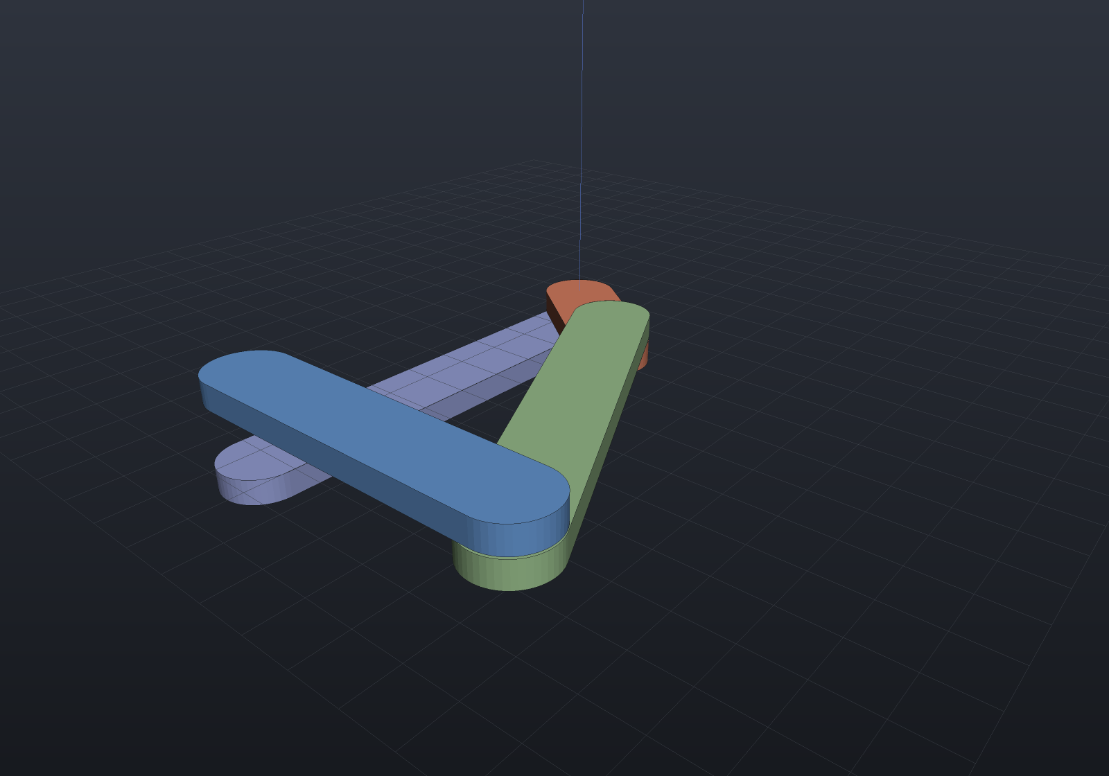
Sweeping, velocities, mobility
Sweep samples a driver across a range with continuation: every step seeds
from the previous converged pose, never the assembled one — reseeding lets the
solver change branch mid-sweep (a four-bar flips elbow-up to elbow-down and the
motion tears). A failed step halves and retries (the solver writes nothing on
failure, so the last good pose is intact), and a sweep that cannot proceed
reports the parameter honestly.
RatesAt computes velocities and accelerations from the analytic Jacobian
(J·q̇ = −∂C/∂t, then J·q̈ = −r̈₀ with the second-order terms assembled exactly),
and Mobility() puts the Grübler/Kutzbach formula beside the measured rank —
disagreement is informative, not an error: overconstrained-but-mobile linkages
(a planar linkage built in space, Bennett, Sarrus) are exactly where the formula
lies and the rank is right.
// A slider-crank (r = 5, l = 20), authored exactly assembled at crank angle 90°.Frame3d Posed(double x, double y, double angle) => Frame3d.FromXY((x, y, 0),    (Math.Cos(angle), Math.Sin(angle), 0), (-Math.Sin(angle), Math.Cos(angle), 0));var rig = new Assembly("engine");var ground = rig.Add(new Part("ground", Shape.Box(4, 2, 1)));var crank = rig.Add(new Part("crank", Shape.Box(4, 2, 1)));var rod = rig.Add(new Part("rod", Shape.Box(4, 2, 1)));var slider = rig.Add(new Part("slider", Shape.Box(4, 2, 1)));double x0 = Math.Sqrt(20 * 20 - 5 * 5);crank.Frame = Posed(0, 0, Math.PI / 2);rod.Frame = Posed(0, 5, Math.Atan2(-5, x0));slider.Frame = Frame3d.FromXY((x0, 0, 0), Vector3d.UnitX, Vector3d.UnitY);
var z = Vector3d.UnitZ;var crankPin = Joint.Revolute(    MateGeometry.Axis(ground, (0, 0, 0), z), MateGeometry.Axis(crank, (0, 0, 0), z), "crank pin");var slide = Joint.Prismatic(    MateGeometry.Axis(ground, (0, 0, 0), Vector3d.UnitX),    MateGeometry.Axis(slider, (0, 0, 0), Vector3d.UnitX), "slide");var mechanism = new Mechanism(rig)    .Ground(ground)    .Add(crankPin)    .Add(Joint.Revolute(MateGeometry.Axis(crank, (5, 0, 0), z), MateGeometry.Axis(rod, (0, 0, 0), z)))    .Add(Joint.Revolute(MateGeometry.Axis(rod, (20, 0, 0), z), MateGeometry.Axis(slider, (0, 0, 0), z)))    .Add(slide);mechanism.Assemble();
// A full crank cycle, 49 sampled frames of pure poses (the animation input format).var study = mechanism.Sweep(MechanismDriver.Angle(crankPin), 0, 2 * Math.PI, frames: 49);if (!study.Completed) throw new Exception(study.ToString());if (Math.Abs(crankPin.Angle - 2 * Math.PI) > 1e-8)    throw new Exception("the unwrapped angle should read a full turn");
// Velocity against the closed form x = R cos θ + √(L² − R² sin²θ), θ = π/2 + t.const double omega = 2.0, t = 0.4;var rates = mechanism.RatesAt(MechanismDriver.Angle(crankPin), t, rate: omega);double theta = Math.PI / 2 + t, s = Math.Sin(theta), c = Math.Cos(theta);double root = Math.Sqrt(20 * 20 - 5 * 5 * s * s);double expected = omega * (-5 * s - 5 * 5 * s * c / root);if (Math.Abs(rates.For("slider").Velocity.X - expected) > 1e-6)    throw new Exception($"slider velocity {rates.For("slider").Velocity.X} vs closed form {expected}");
// Grübler says −2 (spatial formula, planar linkage); the measured rank says 1.var mobility = mechanism.Mobility();if (mobility.Agrees || mobility.MeasuredDegreesOfFreedom != 1)    throw new Exception(mobility.ToString());
Gears, belts, cams
Higher pairs are scalar couplings between joint coordinates — one residual
row each, no new solver. A gear ratio is Δθ₂ = ∓(N₁/N₂)·Δθ₁ (external mesh
counter-rotates), a belt the same with pitch radii, a screw’s pitch the same idea
inside Joint.Screw:
A
Coupling.Gearconstrains the ratio and cares nothing about whether a tooth was ever drawn — the cylinders below carry no teeth at all. For the tooth forms — involute, helical, herringbone, rack, worm, bevel, planetary, cycloidal — and the geometry that generates them, see Gears.
var rig = new Assembly("gearbox");var housing = rig.Add(new Part("housing", Shape.Box(50, 20, 4)));var gearA = rig.Add(new Part("gearA", Shape.Cylinder(10, 4)));var gearB = rig.Add(new Part("gearB", Shape.Cylinder(20, 4)),    Frame3d.FromXY((30, 0, 0), Vector3d.UnitX, Vector3d.UnitY));var z = Vector3d.UnitZ;var pinA = Joint.Revolute(    MateGeometry.Axis(housing, (0, 0, 0), z), MateGeometry.Axis(gearA, (0, 0, 0), z), "pin A");var pinB = Joint.Revolute(    MateGeometry.Axis(housing, (30, 0, 0), z), MateGeometry.Axis(gearB, (0, 0, 0), z), "pin B");var mechanism = new Mechanism(rig).Ground(housing).Add(pinA).Add(pinB)    .Add(Coupling.Gear(pinA, pinB, teethA: 20, teethB: 40));
mechanism.SolveAt(MechanismDriver.Angle(pinA), Math.PI / 2);if (Math.Abs(pinB.Angle + Math.PI / 4) > 1e-8)    throw new Exception($"20:40 external mesh should counter-rotate at half speed, got {pinB.Angle}");
var rates = mechanism.RatesAt(MechanismDriver.Angle(pinA), Math.PI / 2, rate: 3);if (Math.Abs(rates.For(pinB).AngleRate + 1.5) > 1e-8)    throw new Exception("gear rates should follow the ratio exactly");
A cam is a coupling whose law is a profile: CamLaw.FromSketch reads a
radial cam drawn as a Sketch about its pivot — every sampled radius is the
outermost crossing of the sketch’s exact signed distance, and the law between
samples is a C² periodic spline whose slope and curvature feed the Jacobian and
the acceleration analysis. Here the textbook eccentric circular cam lifts a
follower:
var profile = Sketch.Circle(new Vector2d(3, 0), 9);        // radius 9, centre 3 off the pivotvar cam = new Part("cam", Shape.Extrude(profile, 4), Palette.Steel);var follower = new Part("follower",    Shape.Box(8, 14, 8).Translate(0, 7, 2) | Shape.Box(3, 26, 3).Translate(0, 26, 2),    Palette.Brass);
var rig = new Assembly("camshaft");var camOcc = rig.Add(cam);// The follower rides along +Y; at cam angle 0 the profile reaches √(9² − 3²) up.var followerOcc = rig.Add(follower,    Frame3d.FromXY((0, Math.Sqrt(81 - 9), 0), Vector3d.UnitX, Vector3d.UnitY));
var camPin = Joint.Revolute(    MateGeometry.World((0, 0, 0), Vector3d.UnitZ),    MateGeometry.Axis(camOcc, (0, 0, 0), Vector3d.UnitZ), "cam pin");var followerSlide = Joint.Prismatic(    MateGeometry.World((0, 0, 0), Vector3d.UnitY),    MateGeometry.Axis(followerOcc, (0, 0, 0), Vector3d.UnitY), "follower");var mechanism = new Mechanism(rig)    .Add(camPin)    .Add(followerSlide)    .Add(Coupling.Cam(camPin, followerSlide,        CamLaw.FromSketch(profile, followerAngle: Math.PI / 2)));
mechanism.SolveAt(MechanismDriver.Angle(camPin), 2.2);     // the follower rides the profile
var scene = new Scene();scene.AddTab("cam").Add(rig);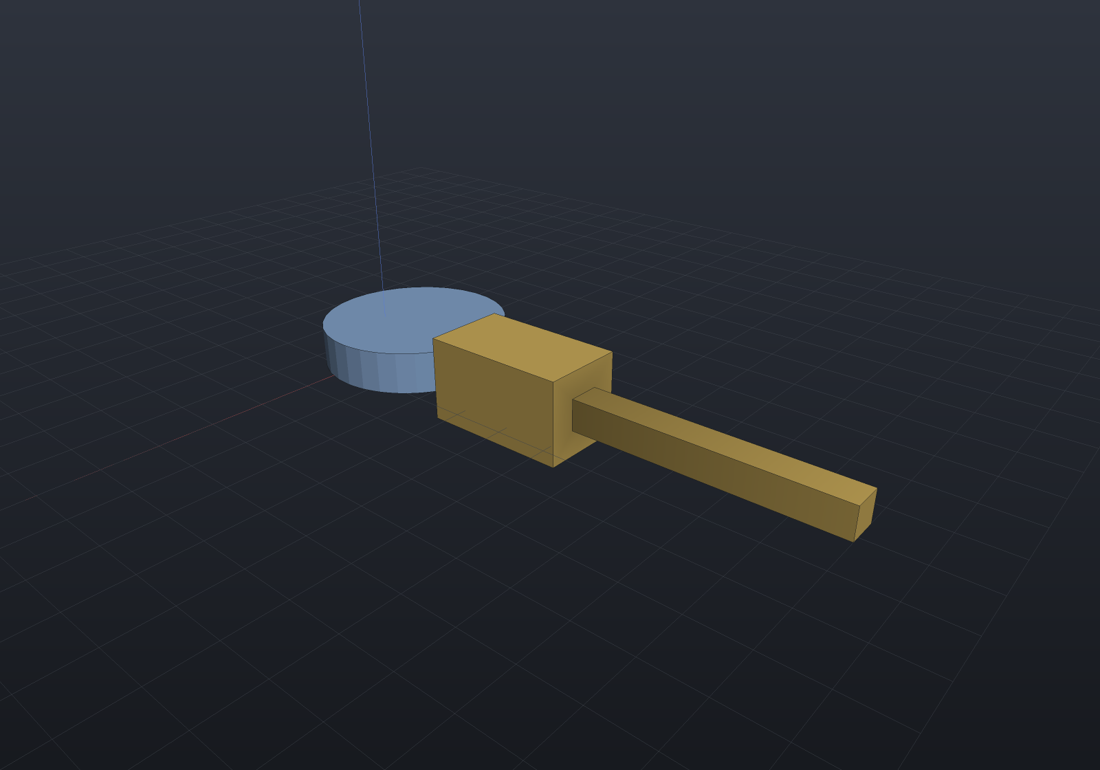
Roller and offset followers, and the pressure angle
A real follower is rarely a knife edge. A roller follower’s centre does not ride
the profile — it rides the profile’s planar offset at the roller radius, and a
planar offset is not a radial one: the shortcut r(θ) + R is wrong by O(R·r′²/r²),
worst exactly where the cam is steepest. CamLaw.FromSketch takes a CamFollower
and reads the offset exactly, with no offset curve ever built: the sketch’s
signed distance is a true planar distance outside the profile, so the roller centre
is the outermost crossing of the isolevel sd = R along the follower’s travel line —
the same march and bisection the point follower gets. An offset follower moves
the travel line off the pivot (positive to the right of the travel direction),
which is the knob a designer turns to improve the pressure angle — reported by
CamLaw.PressureAngle from the law’s own slope via the instant-centre relation
tan φ = (slope − offset)/distance.
The eccentric circle makes every claim checkable in closed form, because the offset of a circle is a circle:
var profile = Sketch.Circle(new Vector2d(3, 0), 8);        // radius 8, centre 3 off the pivotconst double a = 8, e = 3, r = 2;
// Roller compensation: the centre rides the circle of radius a + r, so the law is// e·cosθ + √((a+r)² − e²·sin²θ) — NOT the point law plus r, which misses by 0.12// at θ = π/2 on this very fixture.var roller = CamLaw.FromSketch(profile, CamFollower.Roller(r));roller.Evaluate(Math.PI / 2, out double lift, out _, out _);if (Math.Abs(lift - Math.Sqrt((a + r) * (a + r) - e * e)) > 1e-6)    throw new Exception("the roller centre rides the planar offset");var point = CamLaw.FromSketch(profile);point.Evaluate(Math.PI / 2, out double radial, out _, out _);if (Math.Abs(radial + r - lift) < 0.1)    throw new Exception("the radial shortcut should measurably disagree here");
// An offset follower: travel line 2.5 to the right of the pivot, and the pressure// angle from the law's own slope. On the rise, the offset earns its keep.var follower = CamFollower.Roller(r, angle: 0, offset: 2.5);var offsetLaw = CamLaw.FromSketch(profile, follower);double theta = 4.5;                                        // on the rise (slope > 0)double improved = Math.Abs(offsetLaw.PressureAngle(theta, follower));double plain = Math.Abs(roller.PressureAngle(theta, CamFollower.Roller(r)));if (improved >= plain)    throw new Exception("a positive offset reduces the rise-side pressure angle");
The roller radius never enters the pressure angle (the contact normal passes through
the roller’s centre whatever its radius); for a zero-based catalogue rise over a
prime circle, pass baseDistance: Math.Sqrt(primeRadius * primeRadius - offset * offset)
so the denominator is the follower centre’s true distance.
Limits, dead centres, honest stops
WithLimits puts hard stops on a revolute (degrees) or prismatic (length)
joint. A solve past a stop is rolled back completely and refused naming the
joint; a sweep walks up to the stop and reports it. At a dead centre the
Jacobian loses rank along the driven direction — the sweep detects it (the same
rank machinery behind the DOF report, with a widened threshold for the
diagnosis), names the driven joint and the parameter, and refuses to guess a
branch; the same pose driven from a different joint is harmless and says
nothing.
var rig = new Assembly("rig");var fixedOne = rig.Add(new Part("base", Shape.Box(4, 2, 1)));var moving = rig.Add(new Part("door", Shape.Box(4, 2, 1)));var hinge = Joint.Revolute(    MateGeometry.Axis(fixedOne, (0, 0, 0), Vector3d.UnitZ),    MateGeometry.Axis(moving, (0, 0, 0), Vector3d.UnitZ), "hinge").WithLimits(-45, 45);var mechanism = new Mechanism(rig).Ground(fixedOne).Add(hinge);
var study = mechanism.Sweep(MechanismDriver.Angle(hinge), 0, Math.PI / 2, frames: 19);if (study.Completed) throw new Exception("the sweep should stop at the 45° stop");if (!study.Diagnostics.Any(d => d.Contains("past its stop") && d.Contains("hinge")))    throw new Exception("the stop should be reported by joint name");if (Math.Abs(hinge.AngleDegrees - 45) > 0.5)    throw new Exception("the assembly should be left ON the stop");
Interference and swept volume
CheckInterference runs per-frame clash detection over a study’s sampled poses:
instance bounds are the broad phase, transversal mesh crossing the narrow phase —
so parts resting on each other are not clashes — with intersection volumes
opt-in per confirmed range. A volume is B-Rep-exact where both parts lower to
solids and the boolean of the posed solids accepts the pair (a rotated-pose box
overlap measures its closed form to 1e-9), falling back to the exact mesh boolean
of the display tessellations otherwise — and InterferenceRange.VolumeSource
names WHICH grade answered, because the two carry different error (exact against
the meshes’ chord error) and must never be mistaken for one another. SweptVolume turns the motion itself into a
Shape: implicit-native (the part’s field lowered once and placed per pose),
mesh via Surface Nets, B-Rep honestly impossible.
var rig = new Assembly("rig");var ground = rig.Add(new Part("ground", Shape.Cylinder(3, 2), Palette.Slate));var arm = rig.Add(new Part("arm",    Shape.Extrude(Sketch.Slot(47, 7), 4).Translate(20, 0, 3), Palette.Coral));rig.Add(new Part("post", Shape.Box(4, 4, 18).Translate(0, 0, 9), Palette.Sky),    Frame3d.FromXY((30, 18, 0), Vector3d.UnitX, Vector3d.UnitY));
var pin = Joint.Revolute(    MateGeometry.Axis(ground, (0, 0, 0), Vector3d.UnitZ),    MateGeometry.Axis(arm, (0, 0, 0), Vector3d.UnitZ), "pin");var mechanism = new Mechanism(rig).Ground(ground).Add(pin);
var study = mechanism.Sweep(MechanismDriver.Angle(pin), 0, 2 * Math.PI, frames: 61);var clashes = study.CheckInterference();if (clashes.Clear) throw new Exception("the arm sweeps through the post — that must be reported");
var swept = new Part("swept volume", study.SweptVolume("arm"), Palette.Teal)    { DisplayMode = DisplayMode.Translucent };
var scene = new Scene();var tab = scene.AddTab("sweep");tab.Add(rig);tab.Add(swept);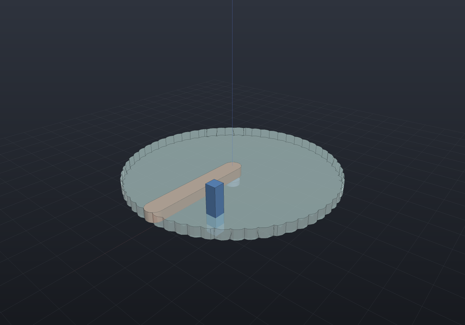
The clash report names the pair and the driver-parameter ranges
(rig/arm × rig/post: [0.42, 0.63]-style); pairs directly connected by a joint
are skipped by default, because a pin modeled at its bore’s exact diameter
interpenetrates once tessellated.
A swept volume built from the study’s own frames inherits whatever frame count the
sweep happened to use, which is not a fidelity setting anyone chose. maxTravel
replaces it with a bound in model units — extra placements are rigidly
interpolated between the recorded frames until no point of the part moves further than
that between consecutive ones:
var rig = new Assembly("rig");var ground = rig.Add(new Part("ground", Shape.Box(2, 2, 1)));var arm = rig.Add(new Part("arm", Shape.Box(20, 2, 2)));var pin = Joint.Revolute(    MateGeometry.Axis(ground, (0, 0, 0), Vector3d.UnitZ),    MateGeometry.Axis(arm, (0, 0, 0), Vector3d.UnitZ), "pin");var mechanism = new Mechanism(rig).Ground(ground).Add(pin);
// Nine frames over a full turn: 45 degrees between placements leaves visible scallops.var study = mechanism.Sweep(MechanismDriver.Angle(pin), 0, 2 * Math.PI, frames: 9);double disk = Math.PI * 100 * 2;                       // radius 10, thickness 2double coarse = study.SweptVolume("arm").ToMesh().Volume();double refined = study.SweptVolume("arm", maxTravel: 0.5).ToMesh().Volume();
if (!(coarse < refined && refined > 0.97 * disk))    throw new Exception($"refinement should close the gap: {coarse:g6} -> {refined:g6} of {disk:g6}");
Travel is measured exactly, as the largest displacement of the part’s own bounding-box corners between two poses — not a rotation angle times an assumed radius — so a body spinning about its own centre costs few extra placements and one on the end of a long arm costs many. The recorded frames are all kept, so refining can only add material, and omitting the bound leaves the geometry bit-identical.
Driving two things at once
SolveAt and Sweep take a list, which is what a 2-DOF mechanism needs: with one
driver the pose is a family and the solver would be picking a member of it. A
cylindrical joint is the smallest honest case — spin and slide on one joint:
var rig = new Assembly("rig");var ground = rig.Add(new Part("base", Shape.Box(4, 2, 1)));var sleeve = rig.Add(new Part("sleeve", Shape.Box(4, 2, 1)));var joint = Joint.Cylindrical(    MateGeometry.Axis(ground, (0, 0, 0), Vector3d.UnitZ),    MateGeometry.Axis(sleeve, (0, 0, 0), Vector3d.UnitZ));var mechanism = new Mechanism(rig).Ground(ground).Add(joint);
var spin = MechanismDriver.Angle(joint);var slide = MechanismDriver.Slide(joint);
var one = mechanism.SolveAt(spin, Math.PI / 4);if (one.RemainingDegreesOfFreedom != 1) throw new Exception("one driver leaves the slide free");
var both = mechanism.SolveAt([(spin, Math.PI / 4), (slide, 3.5)]);if (both.RemainingDegreesOfFreedom != 0) throw new Exception("two drivers pin a 2-DOF joint");
// A sweep moves every driver along ONE parameter -- a coordinated motion (here a// helix: a full turn while sliding 10), not a grid of every combination.var study = mechanism.Sweep([(spin, 0, 2 * Math.PI), (slide, 0, 10.0)], frames: 21);if (!study.Completed) throw new Exception(study.ToString());if (study.Frames[10].Values.Count != 2) throw new Exception("each frame records every driver");
Driving the same coordinate twice is refused by name — one coordinate cannot hold two
targets — while two drivers on one joint driving different variables is the whole
point. MotionFrame.Values carries every driver’s value; Value stays the first
driver’s, so code written for a single-driver study reads exactly what it did.
Rack and pinion, and the cam-law catalogue
A rack and pinion is Δz = r·Δθ, which is a cam pair with a straight law — so that is how it is built, rather than as a fourth kind of constraint. It reads the unwrapped angle, so a rack driven through three turns keeps advancing instead of resetting at every seam:
var rig = new Assembly("rig");var ground = rig.Add(new Part("base", Shape.Box(4, 2, 1)));var pinion = rig.Add(new Part("pinion", Shape.Cylinder(12.5, 4)));var rack = rig.Add(new Part("rack", Shape.Box(120, 6, 4)));var spin = Joint.Revolute(    MateGeometry.Axis(ground, (0, 0, 0), Vector3d.UnitZ),    MateGeometry.Axis(pinion, (0, 0, 0), Vector3d.UnitZ), "pinion");var slide = Joint.Prismatic(    MateGeometry.Axis(ground, (0, 0, 0), Vector3d.UnitX),    MateGeometry.Axis(rack, (0, 0, 0), Vector3d.UnitX), "rack");var mechanism = new Mechanism(rig).Ground(ground).Add(spin).Add(slide)    .Add(Coupling.RackAndPinion(spin, slide, pitchRadius: 12.5));
mechanism.Sweep(MechanismDriver.Angle(spin), 0, 3 * 2 * Math.PI, frames: 25);if (Math.Abs(slide.Displacement - 12.5 * 3 * 2 * Math.PI) > 1e-6)    throw new Exception($"three turns should advance 3 x 2 pi r, got {slide.Displacement}");
For cams, the standard dwell–rise–dwell laws are a catalogue rather than an exercise. What separates them is what happens where a rise meets a dwell — cycloidal and modified trapezoid end with zero acceleration and join a dwell smoothly, while harmonic steps (the classic source of cam noise) and buys the lowest peak velocity in exchange. Peak acceleration factors are 2π, 8π/(2+π) = 4.888 and π²/2 respectively, which is the number you choose between them on:
double span = Math.PI;                                  // a 180-degree risedouble rise = 10;
var cycloidal = CamLaw.Cycloidal(rise, span);var trapezoid = CamLaw.ModifiedTrapezoid(rise, span);var harmonic = CamLaw.HarmonicRise(rise, span);
double Peak(CamLaw law){    double peak = 0;    for (int i = 0; i <= 4000; i++)    {        law.Evaluate(span * i / 4000.0, out _, out _, out double curvature);        peak = Math.Max(peak, Math.Abs(curvature));    }    return peak / (rise / (span * span));}
if (Math.Abs(Peak(cycloidal) - 2 * Math.PI) > 1e-3) throw new Exception("cycloidal peaks at 2 pi");if (Math.Abs(Peak(trapezoid) - 4.8881) > 1e-3) throw new Exception("modified trapezoid peaks at 4.888");if (Math.Abs(Peak(harmonic) - Math.PI * Math.PI / 2) > 1e-3) throw new Exception("harmonic peaks at pi^2/2");
// Chain them into a cycle. Spans are scaled to fill one turn, so a profile stated in// degrees of its own cycle keeps its shape.var profile = CamLaw.Segments(    (90.0, CamLaw.Dwell()),                       // low dwell    (90.0, CamLaw.Cycloidal(rise, 90)),           // rise    (90.0, CamLaw.Dwell(rise)),                   // high dwell    (90.0, CamLaw.Cycloidal(-rise, 90)));         // return
profile.Evaluate(Math.PI, out double top, out _, out _);if (Math.Abs(top - rise) > 1e-6) throw new Exception("the cycle should be at full lift half way round");
A rise clamps outside its own span (zero before, its rise after, with zero slope
and curvature at both), which is exactly what lets Segments chain it without the
composer having to know anything about the laws it is chaining. Continuity across a
joint stays the segments’ business: smoothing it centrally would hide the very property
the catalogue exists to let you choose.
Saving a mechanism
Mechanism.SaveMechanism() writes the whole joint layer as one JSON envelope —
grounds, raw mates, joints, couplings — and LoadMechanism reads it back with
warnings (never exceptions) for anything the model no longer matches. Joint mates
are not restated (they are a deterministic function of the joint’s two ends); what
cannot be re-derived rounds trip as data: the axis joints’ perpendicular reference
directions, and the unwrapped angle history — a crank saved after two full turns
reloads at 4π and keeps counting, which no fresh construction at the same pose could
recover. Cam laws save their factory kind and arguments (a FromSketch law saves its
samples; a FromFunction lambda saves an opaque marker that loads as a warning
unless a resolveOpaqueLaw hook supplies it), and save → load → save is a
byte-identical fixed point:
var rig = new Assembly("gearbox");var housing = rig.Add(new Part("housing", MeshPrimitives.Box(4, 2, 1)));var gearA = rig.Add(new Part("gearA", MeshPrimitives.Box(4, 2, 1)));var gearB = rig.Add(new Part("gearB", MeshPrimitives.Box(4, 2, 1)),    Frame3d.FromXY((30, 0, 0), Vector3d.UnitX, Vector3d.UnitY));var z = Vector3d.UnitZ;var pinA = Joint.Revolute(    MateGeometry.Axis(housing, (0, 0, 0), z), MateGeometry.Axis(gearA, (0, 0, 0), z), "pin A");var pinB = Joint.Revolute(    MateGeometry.Axis(housing, (30, 0, 0), z), MateGeometry.Axis(gearB, (0, 0, 0), z), "pin B");var mechanism = new Mechanism(rig).Ground(housing).Add(pinA).Add(pinB)    .Add(Coupling.Gear(pinA, pinB, teethA: 20, teethB: 40));
// Two full turns of history, then save mid-motion.mechanism.Sweep(MechanismDriver.Angle(pinA), 0, 4 * Math.PI, frames: 17);string file = mechanism.SaveMechanism();
var reloaded = new Mechanism(rig);var warnings = reloaded.LoadMechanism(file);if (warnings.Count != 0) throw new Exception(string.Join("; ", warnings));if (reloaded.SaveMechanism() != file) throw new Exception("save-load-save must be a fixed point");
var crank = (RevoluteJoint)reloaded.Joints[0];if (Math.Abs(crank.Angle - 4 * Math.PI) > 1e-8)    throw new Exception("the unwrapped history must survive: two turns is 4 pi, not 0");reloaded.SolveAt(MechanismDriver.Angle(crank), 4 * Math.PI + 0.5);   // and keeps counting
Loading re-adds every joint, which re-asserts its nominal DOF against the solver’s measured rank — so a file that was valid when written can legitimately load with a warning if the model changed underneath it; the joint is skipped and any coupling referencing it is skipped by name, never guessed at.