3D annotations (PMI)
Parts can carry their own manufacturing information — dimensions, notes, and datum
labels attached to model geometry in 3D space (model-based definition, instead of
2D drawings). Annotations live on the Part, resolve against its geometry, and are
drawn by the viewer with classic dimension graphics: extension lines, arrowheads, and
billboarded screen-constant text. They render in headless/docs output too — the
image below is produced by the same offscreen renderer that made every other picture
on this site.
Dimensions that measure the model
The important annotations are selector-based: instead of storing a number, a
dimension stores a semantic query (the BrepQueries vocabulary the chamfer/fillet
selectors use) and measures the actual geometry every time it resolves. Change a
parameter, regenerate, and the dimension re-measures — the same topological-naming
story as parametric features.
var plate = Shape.Box(40, 20, 5)    .Drill(StandardHoles.Clearance(5), [new(-12, 0), new(12, 0)], depth: 6,        SketchPlane.At((0, 0, 2.5), Vector3d.UnitX, Vector3d.UnitY));
var part = new Part("plate", plate);
// Auto-measured width: the distance between the two X faces (selector re-runs// per resolution, so it tracks parameter edits).part.Annotate(LinearDimension.BetweenFaces(    s => s.PlanarFacesWithNormal(-Vector3d.UnitX).First(),    s => s.PlanarFacesWithNormal(Vector3d.UnitX).First()));
// Thickness, pulled to the front with an explicit placement offset.var thickness = LinearDimension.BetweenFaces(    s => s.PlanarFacesWithNormal(Vector3d.UnitZ).First(),    s => s.PlanarFacesWithNormal(-Vector3d.UnitZ).First());thickness.Offset = new Vector3d(0, -16, 0);part.Annotate(thickness);
// The bore diameter, read from the actual circular edge: "⌀5.5".part.Annotate(RadialDimension.OnEdge(    s => s.Faces.SelectMany(f => f.Edges()).Distinct()        .First(e => e.IsCircular(out var c, out _, out _) && c.X > 0 && c.Z > 2),    diameter: true));
// A hole callout generated from the same spec that drilled the holes,// and a datum label.part.Annotate(HoleCallout.From(StandardHoles.Clearance(5), (-12, -2.75, 2.5), depth: 6));part.Annotate(new DatumLabel((-20, 8, 2.5), "A"));
var scene = new Scene();scene.Add(part);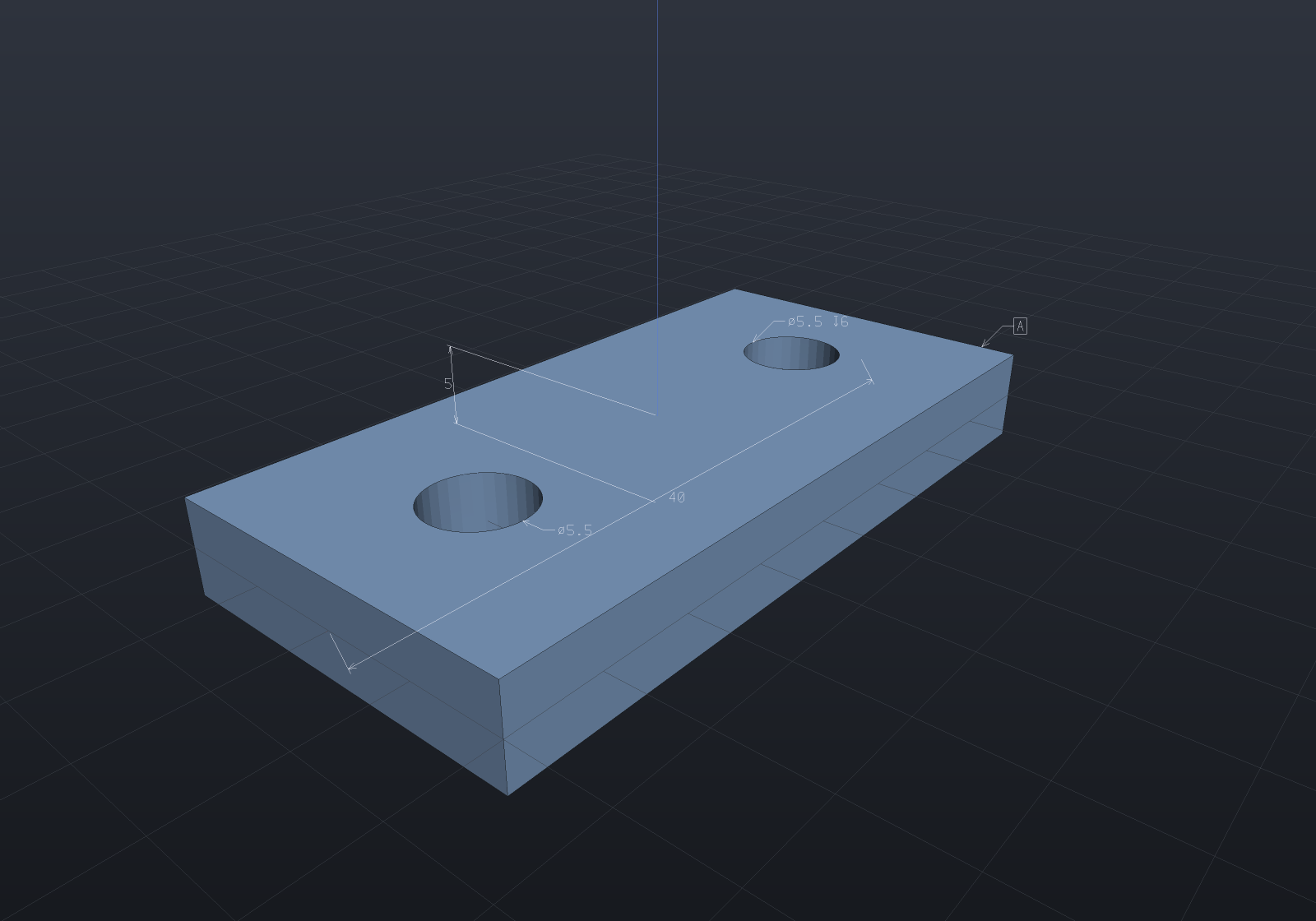
Angles, tolerances, and hole tables
The dimension vocabulary extends to angles, tolerance text, and drilling data pulled straight out of the geometry graph:
// A block with a 15° drafted side, then two counterbored holes in its top.var body = Shape.Box(40, 24, 12)    .Draft(15, neutralOrigin: (0, 0, -6), pullDirection: Vector3d.UnitZ,        faces: s => s.PlanarFacesWithNormal(Vector3d.UnitX))    .Drill(StandardHoles.Counterbored(4), [new(-10, 0), new(10, 0)], depth: 20,        SketchPlane.At((0, 0, 6), Vector3d.UnitX, Vector3d.UnitY));
var part = new Part("bracket", body);
// Angular dimension between the drafted face and the base: the faces' INCLUDED// angle (75°), measured from the actual planes per resolution.part.Annotate(AngularDimension.BetweenFaces(    s => s.Faces.First(f => f.IsPlanar(out _, out var n) && n.Dot(Vector3d.UnitX) > 0.9),    s => s.PlanarFacesWithNormal(-Vector3d.UnitZ).First()));
// A toleranced dimension: the tolerance is text sugar appended to the value.part.Annotate(new LinearDimension((-20, -12, -6), (20, -12, -6)){    Tolerance = ToleranceSpec.Symmetric(0.1),    Offset = new Vector3d(0, -10, 0),});
// Hole-table balloons ("A1", "A2") plus a table note, generated from the SAME// Drill call that cut the holes — nothing transcribed.HoleTable.For(part).Annotate(part, tableAnchor: (0, 18, 6));
var scene = new Scene();scene.Add(part);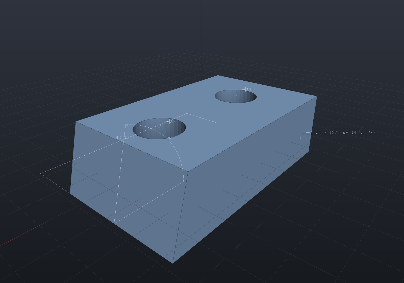
Which side of the part is it on?
By default the overlay is drawn on top of everything, so no dimension can ever be obscured. That is safe and says nothing: a dimension line placed at mid-thickness — the default placement for a face-to-face width — really runs inside the plate, and drawn over the top face it reads as though it were lying on it.
AnnotationDepth.Occluded depth-tests the line work instead. Stretches with material in
front of them are drawn dimmed; the values stay at full strength wherever they sit,
because a dimension’s number is what you are there to read and a half-obscured “40” is
worth nothing. Compare the plate above with the same plate below: the width dimension
sinks into the material and stops crossing its own text, while the bore leader — which
lies in the top face — still reads as being on it.
var plate = Shape.Box(40, 20, 5)    .Drill(StandardHoles.Clearance(5), [new(-12, 0), new(12, 0)], depth: 6,        SketchPlane.At((0, 0, 2.5), Vector3d.UnitX, Vector3d.UnitY));
var part = new Part("plate", plate);
part.Annotate(LinearDimension.BetweenFaces(    s => s.PlanarFacesWithNormal(-Vector3d.UnitX).First(),    s => s.PlanarFacesWithNormal(Vector3d.UnitX).First()));
var thickness = LinearDimension.BetweenFaces(    s => s.PlanarFacesWithNormal(Vector3d.UnitZ).First(),    s => s.PlanarFacesWithNormal(-Vector3d.UnitZ).First());thickness.Offset = new Vector3d(0, -16, 0);part.Annotate(thickness);
part.Annotate(RadialDimension.OnEdge(    s => s.Faces.SelectMany(f => f.Edges()).Distinct()        .First(e => e.IsCircular(out var c, out _, out _) && c.X > 0 && c.Z > 2),    diameter: true));part.Annotate(HoleCallout.From(StandardHoles.Clearance(5), (-12, -2.75, 2.5), depth: 6));part.Annotate(new DatumLabel((-20, 8, 2.5), "A"));
// The one line that differs from the render above.var annotationDepth = AnnotationDepth.Occluded;
var scene = new Scene();scene.Add(part);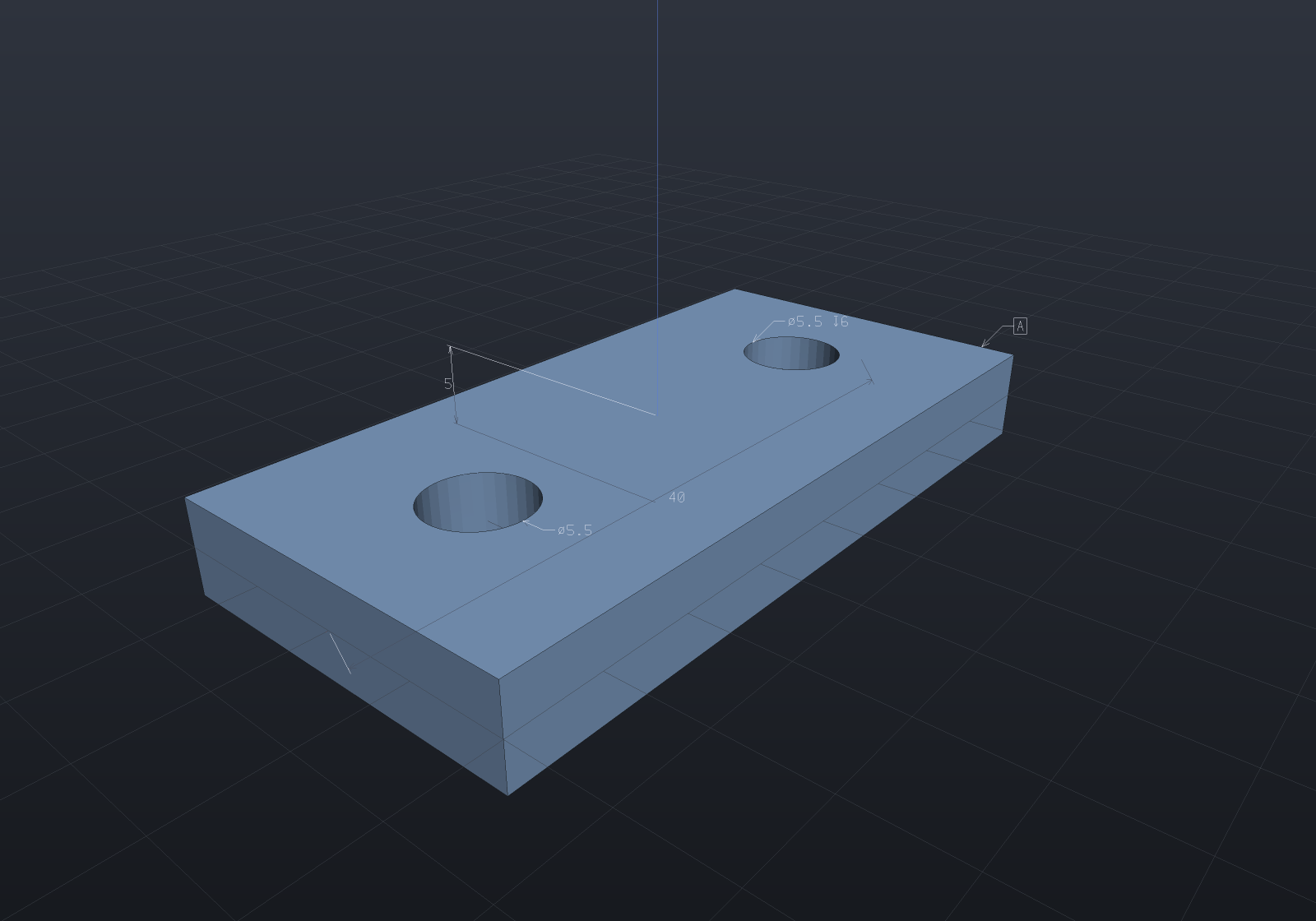
Reach it from the Top / Depth button beside the viewer’s Annot toggle, from
EngrCad.Configure().WithAnnotationDepth(AnnotationDepth.Occluded), from
EngrCad.RenderToImage(..., annotationDepth:), from the MCP screenshot tool’s
annotationDepth: "occluded", or — as above — by declaring an annotationDepth
variable in a docs render: fence.
Two properties are worth knowing because they are decisions rather than accidents:
- Nothing ever disappears. A hidden stretch is dimmed, never dropped, so the overlay stays complete and clicking still selects an annotation you can see (picking is deliberately depth-blind, and stays so under either mode).
- An annotation lying exactly in a face counts as visible. A radial dimension’s leader is coplanar with the face whose bore it measures; the overlay is pulled one pixel toward the eye so that case is settled by decision rather than by which of two rasterizations rounded further.
The pieces
LinearDimension— between two parallel planar faces (LinearDimension.BetweenFaces(selectorA, selectorB), auto-measured plane-to-plane), or between two fixed points (new LinearDimension(a, b)— what the viewer’s interactive Measure tool creates from two clicks).AngularDimension— the angle at a vertex between two rays (new AngularDimension(vertex, a, b)) or between two non-parallel planar faces (AngularDimension.BetweenFaces(selectorA, selectorB)— the faces’ included angle as they open from their shared edge line, i.e. what a drafter dimensions, not the angle between normals). Drawn as extension rays, an arc with arrowheads, and degree text.RadialDimension.OnEdge(selector, diameter: …)— reads the actual radius of anIsCircularedge; textR5or⌀10.LeaderNote/DatumLabel— free text / a boxed datum letter with a leader to a part-local anchor point. Note text may contain'\n'— the stroke font lays continuation lines out stacked (hole callouts use this for their counterbore/countersink lines).- Chain and ordinate styles —
LinearDimension.Chain(points, offset)dimensions consecutive pairs on one shared line;LinearDimension.Ordinate(points, offset, spacing?)dimensions every point from the first (the datum), stacking the lines outward — the baseline style drawings prefer for hole rows, since it does not accumulate per-segment tolerances. - Tolerance text —
Tolerance = ToleranceSpec.Symmetric(0.1)appends “±0.1”,ToleranceSpec.Limits(0.2, 0.1)appends “+0.2/-0.1” (pure text sugar; aLabeloverride wins). - Callout generators —
HoleCallout.From(holeSpec, anchor, depth)andThreadCallout.From(threadSpec, anchor, depth?)produce standard callout text (“⌀5.5 ↧6”, “M6×1 ↧12”) as leader notes, straight from the specs used to cut the geometry. - Hole tables and auto callouts —
HoleTable.For(part)reads everyDrill/ThreadedHolecall out of the part’sShapegraph (one lettered row per call, in call order) andAnnotate(part, tableAnchor)attaches per-hole balloons (“A1”, “B1”) plus the table as a multi-line note;HoleAnnotations.AutoAttach(part)is the lighter option — one callout note per call, anchored at its first hole, with an “N× ” count prefix. Labeloverrides the formatted text (“10 REF”);Offsetplaces the dimension line or leader (leave it zero for a screen-space default).
In the viewer, annotations are on by default whenever a scene carries any (the Annot toolbar toggle hides them), drawn on top of the model unless the Top / Depth cycler beside it asks for the depth-tested reading above, and posed by the instance transform — assembly instances show their part’s annotations in place. The Measure toggle turns clicks into surface-point picks: two picks create a transient point-to-point dimension, Escape clears it. Annotations are pickable: clicking within a few pixels of a dimension’s lines or text selects it (drawn in selection gold, its text reported in the status bar); clicking it again — or empty space — deselects.